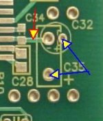
We dont know for certain if its either C31 or C34 OR both C34 and C31...based on my findings I had to remove C31 to remove distortion and the crlrect voltages then showed up on pins 9,10,11 of 9023. Both Atupi and Gary had one or the other but not both populated.
We know for sure its either C35 or C32 but not both.
I cannot see from angle of your photo but you need to check orientation of C7.
i'd say stick with C34 and keep components to the top side. Because of it's proximity it is very important.
C32 and C35 are essentially the same cap, just different footprints. It may have been better to have C32 also marked as C35?
Last edited:
That's the definition/clarity we needed. Same idea just stated more ditectly as it came up early in the thread. Seems perfectly clear now by looking at the board. 😀 
Attachments
Last edited:
one more DAC lives. All IC pins have been continuity checked and voltages look OK. Need to take a break now, hopefully sweet music later.
These boards are beautiful to work with by the way.
Thanks to all who have gone before for the build tips 🙂
Looks great and soldering is top quality.
Please share your soldering technique.
i'd say stick with C34 and keep components to the top side. Because of it's proximity it is very important.
C32 and C35 are essentially the same cap, just different footprints. It may have been better to have C32 also marked as C35?
Is that what you did? you did not populate C31?

Passive, can you tell us what size and type of solder - and the tip size you used?
solder is good 'ol 60/40 from banzai music - very good solder indeed, flows beautifully but My main weapon is Insat Super Flux, brilliant flux for smd. Look it up 😉
My iron is metcal/oki PS-800 and the tip is a 2mm chisel tip.
Looks great and soldering is top quality.
Please share your soldering technique.
Thanks buddy, tin target pads first keeping surface amount quite thin, add more flux to pads and component then place component over tinned pads.
Apply tip to pad and component and the solder will flow over contacts. Do not add more solder unless necessary. After inspection re-flux and flow suspect contacts.
For IC's I gently tin the pins a few at a time, carefully blowing and cooling the chip before continuing. Place the IC on the tinned pads with more fluc then fix corners and check alignment. Finish by carefully pulling the iron tip across the pads and pins. Correct any bridges with flux and heat. No solder wicking is necessary if the right amount of solder is used.
Continuity check all IC pins after cleaning.
Is that what you did? you did not populate C31?
Correct - no C31 is fitted on my board.

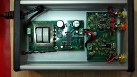
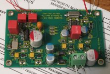
Just to put to bed the discussion on what caps to mount on the NEG pins - C32/C35 and C31 or C34 or both, I finished a 2nd V3 board and mounted 1uf ceramic caps for both C31 and C34 and used the same 4.7uf MKS cap for C35 that I used in the first build. This board works fine and sounds good as does the first board. I'd say that each person can experiment here and there is no set rule. I've attached a picture of this latest build.
---Gary
p.s. I also use a Metcal soldering iron, which is a great tool. One can buy used ones for decent prices on ebay. Having a good soldering iron makes this project much easier. The only thing more important is having really good magnifying glasses so that one can see the small parts.
---Gary
p.s. I also use a Metcal soldering iron, which is a great tool. One can buy used ones for decent prices on ebay. Having a good soldering iron makes this project much easier. The only thing more important is having really good magnifying glasses so that one can see the small parts.
Attachments
Last edited:
Just to put to bed the discussion on what caps to mount on the NEG pins - C32/C35 and C31 or C34 or both, I finished a 2nd V3 board and mounted 1uf ceramic caps for both C31 and C34 and used the same 4.7uf MKS cap for C35 that I used in the first build. This board works fine and sounds good as does the first board. I'd say that each person can experiment here and there is no set rule. I've attached a picture of this latest build.
---Gary
p.s. I also use a Metcal soldering iron, which is a great tool. One can buy used ones for decent prices on ebay. Having a good soldering iron makes this project much easier. The only thing more important is having really good magnifying glasses so that one can see the small parts.
nice job gary... A resting heart rate of 25 bpm would be handy.
I took your advice of higher capacitance for the dac power rail decoupling and 3.3uf input cap.
I would say C34 is mandatory and C31 is optional extra bypass for a film or elko in C35 position. If I do experiment it will be with the neg pin decoupling either with film/ceramic like you or maybe an oscon.
Last edited:
That's the definition/clarity we needed. Same idea just stated more ditectly as it came up early in the thread. Seems perfectly clear now by looking at the board. 😀
C34 is mandatory as it is closest to the pin, then it's either a low ESR electrolytic cap for C32 or a SAL-RPM aluminium pearl cap for C35 (I thought that would be clear as it seems ultra obvious one can't solder both as one hole is shared). If you wish you can use the pads for C31 (at the underside of the PCB) for soldering an extra SMD cap. C31 can always be soldered but keep in mind when a tantalum cap is used where the + must be connected ! Yes to GND ! The negative pin of the ES9023 is sensitive and I thought it would be nice to have pads for experimenting with caps but I see it gives confusion to give choices (isn't it always like that?) 😉
Often I use 4.7 Panasonic FC for C32 and an SMD 4.7 µF tantalum for C31 at the underside of the board (or PPS 1 µF in SMD or 1 µF ceramic MLCC X7R). Too many choices really but I thought you all liked choices....
IMO make total capacitance at the negative pin of ES9023 not higher than 22 µF and I even recommend to stay around 10 µF. Datasheet value of 1 µF really is not enough (visible on oscilloscope). More than 10 µF does not make things significantly better which might have to do with the high switching frequency of the charge pump inside the ES9023. I think many will agree on keeping the total value around 10 µF. OK, now the waiting is for one of you that says 100 µF sounds better 😀
Last edited:
Well that puts it to rest 🙂 Thanks Jean-Paul.
Been plaaying Subbu dac all day in preparation for a "dac-off" tonight.
Been plaaying Subbu dac all day in preparation for a "dac-off" tonight.
I compared my 2 V3 DACs - both with C35 4.7uf MKS and 1uf ceramic C31. One skipped C34 and the other had another 1uf ceramic for C34. The version with 1uf for C34 sounded very, very slightly better so I added this to the other DAC. So I'm done tweaking the NEG supply - this sounds good to me.IMO make total capacitance at the negative pin of ES9023 not higher than 22 µF and I even recommend to stay around 10 µF. Datasheet value of 1 µF really is not enough (visible on oscilloscope) but more than 10 µF does not make things significantly better. OK, now the waiting is for one of you that says 100 µF sounds better 😀
---Gary
p.s. I experimented with C17, the decoupling cap for the 50Mhz oscillator Q2 and decided that I like a ceramic cap here instead of the BOM 4.7uf tantalum. I used some 0.22uf SMD ceramics I had lying around but haven't experimented with values. But the ceramic is a nice improvement over the 4.7um tantalum.
C34 must be used, that is correct. Tweaking with the other caps is nice but the cap closest to the negative pin has impact on the total result.
You are probably right in using a ceramic cap for C17. In an early stage I had oscillating MIC regs twice and one of them was for the XO. I quickly changed the 1 µF ceramic to 4.7 µF tantalum with higher ESR and the problem was solved. This surprised me as the bead is between the reg and the cap. So there is added resistance which should prevent the MIC from oscillating.
After reading your and others comments it seems more logical to use ceramic caps for C17. I now occurs to me I maybe had a bad MIC that time. Recently I used 1 µF ceramic caps again (technically it must be better) for C17 and had no problems with any of the boards. To be honest I think changing the advice again in this stage creates confusion but it is up to you this time to decide OK ? Let me know.
To all: I am very sure that ceramic caps should not be used at the outputs of MIC regs though. They will oscillate. This phenomenon can easily be tested and the problems do repeat themselves.
And.... don't keep me waiting ! Do you like it ? Is it the winner ? 😉
You are probably right in using a ceramic cap for C17. In an early stage I had oscillating MIC regs twice and one of them was for the XO. I quickly changed the 1 µF ceramic to 4.7 µF tantalum with higher ESR and the problem was solved. This surprised me as the bead is between the reg and the cap. So there is added resistance which should prevent the MIC from oscillating.
After reading your and others comments it seems more logical to use ceramic caps for C17. I now occurs to me I maybe had a bad MIC that time. Recently I used 1 µF ceramic caps again (technically it must be better) for C17 and had no problems with any of the boards. To be honest I think changing the advice again in this stage creates confusion but it is up to you this time to decide OK ? Let me know.
To all: I am very sure that ceramic caps should not be used at the outputs of MIC regs though. They will oscillate. This phenomenon can easily be tested and the problems do repeat themselves.
Well that puts it to rest 🙂 Thanks Jean-Paul.
Been playing Subbu V3 DAC all day in preparation for a "dac-off" tonight.
And.... don't keep me waiting ! Do you like it ? Is it the winner ? 😉
Last edited:
JP - I am not sure if the "you" in "it is up to you" refers to me or the general community building the DAC. But if you ask my opinion, the shift to a ceramic cap for C17 is highly recommended and I'd risk the confusion for better sound quality. After trying it on one DAC, it was obvious that I needed to do it on the other one.After reading your and others comments it seems more logical to use ceramic caps for C17. I now occurs to me I maybe had a bad MIC that time. Recently I used a 1 µF ceramic cap again for C17 and had no problems. To be honest I think changing the advice again in this stage creates confusion but it is up to you this time to decide OK ? Let me know.
---Gary
Yes I did mean you Gary. "We" are all trying to improve devices and "you" have experimented more than enough with the V2.6, beta and final V3 boards so/and your opinion is valuable. Since I experienced no problems anymore when using ceramic caps for C17 on the last series I soldered I think using ceramic caps for C17 is completely safe. I lack the time to compare DACs sound wise right now but I trust your expertise on this one. So...
To all: parts change for C17 for better performance of the Subbu V3 DAC . After testing by GaryB using an X7R 1 µF 16 V ceramic cap for C17 is recommended. You can use the same caps you used as input caps of the MIC regulators. I will ask Subbu to change this in the schematics etc. I would not try to remove the 4.7 µF tantalum if you already had trouble building the DAC. Removing SMD parts can end up in PCB traces peeling off the board. You have been warned.
The Subbu V3 won't break down or something like that when using a tantalum cap for C17. When you use a 1 µF ceramic cap for C17 the DAC will perform even better than it does now with the tantalum cap.
Last edited:
ok JP, will swap C17 for ceramic I have some spare.
If anybody in the UK or EU needs a spare 1uf ceramic then get in touch. I have a few for some reason.
If anybody in the UK or EU needs a spare 1uf ceramic then get in touch. I have a few for some reason.
I would not try to remove the 4.7 µF tantalum if you already had trouble building the DAC. Removing SMD parts can end up in PCB traces peeling off the board. You have been warned.
For those brave souls who are willing to brave the wrath of JP and try and remove their already installed 4.7uf caps, I can recommend two techniques. The first is very simple if you have the right tools. Use two soldering irons and heat up both ends of the capacitor. With the solder on both ends melted, one can use the soldering irons as tweezers and just lift the capacitor off of the board. This is what I do.
Or one can buy a Chip Quik SMD Removal Kit, which contains a low temperature solder. The melting temperature of the solder is so low that one can melt one side of the part and then melt the other side and both ends will remain molten long enough to lift off the part. This is useful for parts with more legs such as oscillators or ICs. It's overkill when just removing a capacitor.
---Gary
- Home
- Source & Line
- Digital Line Level
- Build thread - building the Subbu DAC V3 SE