Yes. Please check carefully after cleaning the PCB if you have shorts, solder blobs between or behind WM8804 pins etc. I see you used SAL RPM caps, very good.
Beware, listening to this DAC can be addictive.
Beware, listening to this DAC can be addictive.
Last edited:
I ll definitely do cross check if anything is omitted or missing or bridged or too much addictive 😀
Only listen to it when you got home from work not when you are going to work.
And ....think of C17....
And ....think of C17....
C17 is sorted, thanks to passive420.
I ll use for testing supplied with bom and swap for new part if everything is ok.
I ll hook it with not build yet JG buffer which should bring it even further to the audiophile land of plenty 😀
I ll use for testing supplied with bom and swap for new part if everything is ok.
I ll hook it with not build yet JG buffer which should bring it even further to the audiophile land of plenty 😀
Hi All
So C17 must be replaced using X7R 1uF ceramic cap vs tantalum.
May this 1210 package Murata ref GRM32RR71H105KA01K be a good choice ?
I've noticed C7 marking orientation error, maybe it will be usefull to stick it on first post 😉
Regards
Phil
Thank you Phil for C7. So the mark of the polarized tantalum cap is near L2 now. Is there some problems if switched on the PSP with the bad C7 position ? (8804 dead ?) Any consequence on U5 polarity (now destroyed on my pcb after checking a negative out voltage with u5)?
Trying out and measuring. Originally I wanted the cap to be between the pins so at the underside of the board but then it would be connected to the pins of the XO only with vias. So I accepted the longer trace and choose a larger value cap. BTW Fox says using 10 nF is to minimize power supply noise but we used a very low noise power supply with a bead to the XO. In this case it is more for the noise that the XO itself generates 😉 Cool that Abracon gives an example how to layout the XO PCB tracks (never saw that one before). I haven't used Abracon XOs myself AFAIK. Many XO's already have an internal small cap for decoupling.
Take the data sheet of ES9023 for example. The given values for many caps are absolute minimum values I found out. Probably because of cost as cost is the factor to take into account in this industry, not quality. So when you build a prototype you will scale up with values and in this case you see an immediate improvement with the Vneg cap for instance which is nice. I recall a guy that shove ES9023 aside as it was not good enough in his opinion buit when he used a larger cap for the Vneg he totally changed his opinion. Some part changes are harder to distinguish though ...
But exactly these discussions are the reason we don't want the schematic published as these matters can take ages and everybody has a (different) opinion on it. Opinions don't build DACs. Before you know it all components will be discussed. Fine with me but I won't participate. I built X prototypes and tested many values for making it possible that people can enjoy 1 good sounding V3 DAC after only a few hours labour.
I always feel grateful when the more knowledgeable doesn't mind to spend a few online cycles to explain the why. It is priceless to learn from the experienced 🙂 What I love to learn is the thinking process itself, not one value vs the others. Greatly appreciated for the explanation, JP.
Last edited:
There is a similar discussion going on over on the F5 thread. NP has some sage advice.😀 (Post #13635)
Last edited:
But most probably I cannot put it in front and run wires to the back of enclosure where all components are ?
Why Not ? The BNC, Toslink and USB are all at the end of 12" to 16' cables. A few more inches (shielding where needed) can't make that much difference.
Attachments
Last edited:
Ok. Before I arrange all parts, which consist of:
Pre with source selection
Dac+psu
JG buffer + possibly salas psu
I ll ask for your advise
Pre with source selection
Dac+psu
JG buffer + possibly salas psu
I ll ask for your advise
As a moderate audio fundamentalist I can tell any change from a simple good quality 75 Ohm BNC (both sides!) with coax or just 2 untwisted wires to the PCB will deteriorate final results. 75 Ohm BNC really is the way to go. Toslink is for tossers 😀
In a world of "features" one should not forget that most devices perform best at doing one task. The KISS principle at work so better keep functionality low to an absolute minimum for maximum performance. Sounds dogmatic because it is. There are more than enough devices that work fine but our DAC should perform stellar. At least that was the initial thought when we decided on a 4 $ chip 🙂
BTW V3 can accept Toslink, you could use this from our friends at Twisted Pear:
http://www.twistedpearaudio.com/digital/torx.aspx
It shows the man has gone through a lot of DIYers.
In a world of "features" one should not forget that most devices perform best at doing one task. The KISS principle at work so better keep functionality low to an absolute minimum for maximum performance. Sounds dogmatic because it is. There are more than enough devices that work fine but our DAC should perform stellar. At least that was the initial thought when we decided on a 4 $ chip 🙂
BTW V3 can accept Toslink, you could use this from our friends at Twisted Pear:
http://www.twistedpearaudio.com/digital/torx.aspx
There is a similar discussion going on over on the F5 thread. NP has some sage advice.😀 (Post #13635)
It shows the man has gone through a lot of DIYers.
Last edited:
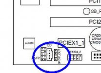
A nice little trick if you use a PC and the motherboard has the pins - make a one or two port BNC adapter from a back-plane slot cover. This one allows both in and out for S/PDIF, but most have at least the out. Just signal and ground and you have a clean feed without going through extra hardware/software on the motherboard.
Attachments
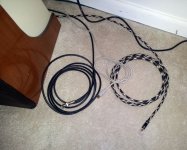
OMG ! We are all gonna die ! Bob, there are input and output wires in the same cable together. If you do it like that make sure both "hot" wires at least have their own shielding.
Motherboard ? When using a pc for audio then Toslink would have the advantage of galvanic separation...probably USB is the better choice for computer audio despite its even more complex demands. Never would have thought anyone would use an SPDIF Subbu V3 on a computer !
Motherboard ? When using a pc for audio then Toslink would have the advantage of galvanic separation...probably USB is the better choice for computer audio despite its even more complex demands. Never would have thought anyone would use an SPDIF Subbu V3 on a computer !
- Home
- Source & Line
- Digital Line Level
- Build thread - building the Subbu DAC V3 SE