Same sound and behaviour from my DAC before replacing 50mhz XO.
A non smd xo was very hepful to decide Xo is dead.
A non smd xo was very hepful to decide Xo is dead.
Gosh I hope I dont have to replace XO again. I dont have any other part to replace it with to test. By end of this I will be an expert in probing 🙂 I do enjoy troubleshooting though.
SUCCESS !!!!!!!!!!!!!!!!!!!!
I removed C31 from underside of pcb and voila !!! Sweet music 🙂
Bob, I was getting the same/similar results as you with 9023 pins 11,12,13. Could not see any issues with C32 either like you.
Try it and let us know. btw my voltages lined 100% with Atupi's so thats a solid reference for everybody.
Now to put it in chassis and compare it to my Schiit Bitfrost Uber DAC.
Last edited:
Here is what I have as lessons learnt:
1. work close to table, easy to lose parts
2. get good magnification - I have 4x magnifier with light and was strong enough to see parts without strain
3. only use flux on parts with lots of legs like 8804, 9023
4. use iron with enough heat to just melt solder
5. tip iron with solder and then apply to one smd part while holding down with tweeser or anything else that will keep it from moving. Then solder other side of smd.
6. check polarity of C7
7. use ONLY C32 or C35
8. use ONLY C34 or C31
9. check all voltages on Lpads (post 57)
10. check all voltages based on Atupis readings (post 256)
11. in worst case, check voltages taken from build 2.6 (post 186)
Last edited:
Congratulations! Great job working through the debug process and coming out with a working DAC.SUCCESS !!!!!!!!!!!!!!!!!!!!
I just fired up my V3 and it seems to be working fine as well. As many pointed out, soldering in Q2 was tougher than I remember in the past. I pretinned all the pads and then soldered one pad down and used tweezers to align the oscillator while keeping that pad hot. After that, I soldered the other pads and used solder wick to remove excess solder. Seems to have done the trick.
---Gary
Attachments
Good pointer Gary, pre-tin the pads before soldering parts. And if you still struggle with Q2, just put it on its side and join the pads with leftover leads from previous projects.
So I need to ask Gary and Atupi, did you remove C31 and only have C34?
So I need to ask Gary and Atupi, did you remove C31 and only have C34?
did you remove C31 and only have C34?
I used C31 and C35 and left C34 unpopulated. I don't think there is any problem using both C31 and C34. You probably overheated your C31 and damaged the part. Thus removing it fixed your problem.
I'll experiment later with adding different values of cap for C34 and see if that has any benefit.
---Gary
Congratulation, don't you feelSUCCESS !!!!!!!!!!!!!!!!!!!!
I removed C31 from underside of pcb and voila !!! Sweet music 🙂
Bob, I was getting the same/similar results as you with 9023 pins 11,12,13. Could not see any issues with C32 either like you.
Try it and let us know. btw my voltages lined 100% with Atupi's so thats a solid reference for everybody.
Now to put it in chassis and compare it to my Schiit Bitfrost Uber DAC.
 came early 😀
Fantastic Neville & Gary!!! Great perseverance that helps us all enormously. I was late on the order and won't be able to rebuild for a day or two. We will be patiently awaiting your reviews of the sound - but I know that big "Swooshing Sound" we hear is JP taking a big relaxing deep breath. 😀 

Last edited:
So I need to ask Gary and Atupi, did you remove C31 and only have C34?
C31 not populated, only C34.
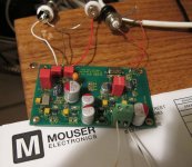
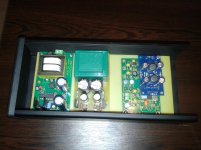
Quick picture of my project: Subbu DAc+Joachim Gerhardt buffer+separate psu for buffer.
Attachments
Christmas sure came early - Thx Fred 🙂 Need to warm up the F5 and Aikido tube preamp and get some serious listening done 🙂
Nice case atupi - so if you did not populate C31 and Gary did not populate C34 that can only confirm one or the other ??
Nice case atupi - so if you did not populate C31 and Gary did not populate C34 that can only confirm one or the other ??
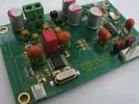
one more DAC lives. All IC pins have been continuity checked and voltages look OK. Need to take a break now, hopefully sweet music later.
These boards are beautiful to work with by the way.
Thanks to all who have gone before for the build tips 🙂
These boards are beautiful to work with by the way.
Thanks to all who have gone before for the build tips 🙂
Attachments
Last edited:
Very nice soldering !! Starting to see a wide variety of cap choices. Interesting and will surely lead to some good sound quality comparisons.
well done Passive420. Curious if you populated C31 and C34? What is the make of those orange "blob" caps?
Bob wish you could finish yours up this weekend 🙂 I bet your old parts work and it was just C31?
Bob wish you could finish yours up this weekend 🙂 I bet your old parts work and it was just C31?
All depends on Mr. Mailman. I did try mine without C31 but something additional was wrong. Any comments on the V3 sound?
Pretty smooth right out of the box compared to by Schiit Bitfrost. I am going to be sitting down comparing all night tonight.
well done Passive420. Curious if you populated C31 and C34? What is the make of those orange "blob" caps?
Bob wish you could finish yours up this weekend 🙂 I bet your old parts work and it was just C31?
Thank you Bob and Neville, actually boys I'm reading back through your posts to establish if I have it correct regarding C31 / 34 etc - So far only C35 is populated with BC128 10uf RAL cap.
The orange blob caps are vishay BC128 10uf/25v solid aluminium caps I have had lying around in the parts box for ages. Nice to able to use them finally.
Spdif input cap is 3.3uf mks, C22 is 470uf polymer.
Last edited:
We dont know for certain if its either C31 or C34 OR both C34 and C31...based on my findings I had to remove C31 to remove distortion and the crlrect voltages then showed up on pins 9,10,11 of 9023. Both Atupi and Gary had one or the other but not both populated.
We know for sure its either C35 or C32 but not both.
I cannot see from angle of your photo but you need to check orientation of C7.
We know for sure its either C35 or C32 but not both.
I cannot see from angle of your photo but you need to check orientation of C7.
- Home
- Source & Line
- Digital Line Level
- Build thread - building the Subbu DAC V3 SE