Aleph-x is an XA series amp clone-ish by G.Rollins. May have been developed partially in parallel, not sure on the timing, all the IP are belong to Nelson though.
The J-X is from my understanding a Aleph-J with susy added ... I haven't followed that project at all so could be off the mark. qusp will be sure to correct me there I'm sure 🙂
I vote you send your spare dac to me 😀
Dual NTD1 would indeed by a beastly setup and need a beastly man to relocate such a device when fully constructed along with all the ancillary devices! qusp's house isn't going to blow away, its fixed to the Earth by all of the heatsinks from his NTD1 and amps! 😀
Last edited:
correct, the AX was an attempt to reverse engineer the XA series, but has a few differences and was a tricky build that wasnt without its share of problems wrt stability, it was endorsed by papa as a thought experiment. it has a mosfet input stage and is capable of a higher output due to the higher voltage and current in the VAS vs the AJX.
the AJX has a Jfet input VAS and is simply a pair of Aleph Js matching the original schematic, but the Peter Daniels boards have 2 different CCS options. these have been designed so they can be used as is as a SE input/output amp, as well as allowing 2 boards to be tied together with an optional input board that adds the crosscoupled X'd feedback and is thus what is called a balanced single ended amp. uses all N channel output devices and will take SE or balanced input
the AJX has a Jfet input VAS and is simply a pair of Aleph Js matching the original schematic, but the Peter Daniels boards have 2 different CCS options. these have been designed so they can be used as is as a SE input/output amp, as well as allowing 2 boards to be tied together with an optional input board that adds the crosscoupled X'd feedback and is thus what is called a balanced single ended amp. uses all N channel output devices and will take SE or balanced input
First I want to make compliments to all that have contributed to this excellent thread! To opc especially for all the engineering and support and also to qusp.
To run the output signal directly to my poweramp (I will use the ESS internal volume control) I need an unbalanced output signal. It could be that I have missed it in this long thread but has anyone tried an output transformer connected between the drains to go from balanced to unbalanced? One of the requirements is to (always!) have zero volts between the two drains. Legato III has a balancing potentiometer in negative supply line to achieve that. But since the D1 produces quite some heat and also during warming up DC conditions can vary this could be troublesome. Any thoughts?
Are there other unbalanced solutions I should consider?
Peter
Hi Peter,
I had mentioned this type of connection method somewhere back in the main development thread, but like you, I would worry about small DC offsets between the two drains saturating the core of the transformer. I'm sure you could get it to within a few mV across the drains, but it will indeed drift by small amounts over time. This might be fine with some transformers, but others certainly won't tolerate even a few millivolts.
What I would suggest is using a centre-tapped transformer and putting a single high quality cap between the two windings. This still gives you DC decoupling, but saves a cap and seems to be the more elegant way to go.
Overall though, I don't really like transformers anywhere in the signal chain, and I would personally just run this single ended if you were going to go that way. You'd get lower distortion and (in my opinion) better sound if you just took the signal off one drain to ground. If you want to preserve the performance and still go single ended, then I would suggest an instrumentation style amp with LME49990 or AD797 op-amps. You could also use a single LME49990 as a differential amp.
Regards,
Owen
First I want to make compliments to all that have contributed to this excellent thread! To opc especially for all the engineering and support and also to qusp.
To run the output signal directly to my poweramp (I will use the ESS internal volume control) I need an unbalanced output signal. It could be that I have missed it in this long thread but has anyone tried an output transformer connected between the drains to go from balanced to unbalanced? One of the requirements is to (always!) have zero volts between the two drains. Legato III has a balancing potentiometer in negative supply line to achieve that. But since the D1 produces quite some heat and also during warming up DC conditions can vary this could be troublesome. Any thoughts?
Are there other unbalanced solutions I should consider?
Peter
I think it is very easy to get a unbalanced output.
The normal DAC Output uses to I/V stages per channel. One for the positive output and one more for the negative output.
Stereo you have 4 output stages.
You only need to use the + output of the Buffalo DAC and wire it to one output stage per channel. The other output of the Buffalo board (the negative signal) is the same, only inverterted.
So you get a unbalanced output. You need only two FETs for Stereo and you get only half of the heat.
My DAC takes more than 60 Watt for the banced outputs.
I use the DAC together with my Aleph-X.
I will post some photos of the DAC here in two or three weeks, when it is completely finished.
A dual mono design with two Buffalo III boards using the normal DAC Board with four FETs for balanced output is possible.
But I think you get not much sound improvement.
@pinnocchio
Its nice that you start building a Aleph-X
Here are some pictures of mine.
See #389
http://www.diyaudio.com/forums/pass-labs/166784-pictures-your-diy-pass-amplifier-39.html
It sounds great! You will not need one more other amplifier.
Regards
Horst
Sorry their are a few english mistakes in my post.
And today I can not edit it.
It would be easier for me to write it in german, but here we are in a english speaking forum.
And today I can not edit it.
It would be easier for me to write it in german, but here we are in a english speaking forum.
Hello,
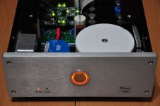
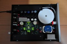
now my DAC is ready. A long journey is over
It takes a lot of coffee to get the many good ideas I needed to finish it in this high quality.🙂
The sound is very impressive. Now I get much more micro details from the music. and I can hear very long with it without feeling any distortion. The dynamic is very good.
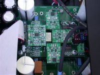
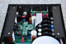
The four high quality output capacitors I bridged with four silver micas 56nF (new old stock) from the customer Jahre.
Power consumption is 67 watts.😱
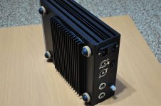
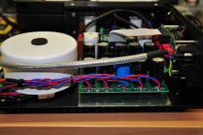
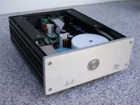
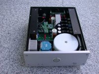
Therefore, I needed to change much details of the original case I ordered from Hifi2000.
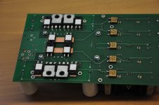
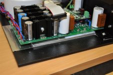
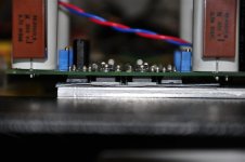
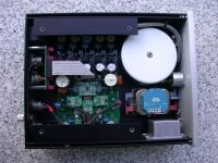
It got a new 5mm powder coated bottom plate, a button heat sink and four L-angle heat sinks (I hope you can see it on the pictures) who are coupling the heat from the bottom side to the top side.
The isolation and thermal coupling of the FETs and Caddock resistors to the bottom plate I made with a combination of a high-tech 0,5mm 86/300 Kerafol and a 86/82 Kerafol red.
Without modify the original case it is not possible to dissipate the heat of the output stages in this case!
The weight is about 6,8 kg
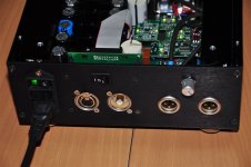
I use a 100 VA custom made transformer with 5 different windings (4x 40V and 1x 9V).
On the backside there is the possibility of changing the output volume.
With the I/II switch I can change between the AES/EBU and the SPDIF Input.
I don’t want to have it on the front side, because normally I only use the AES Input.
With the switch I only change one bit of the remote Input of the Buffalo III.
So I easily can switch between Input one and Input two of the 4-Input board.
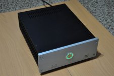
If you switch on the DAC with the main switch on the backside, the front taster lights green.
With a light press to the front taster the Eltako ES61 switches on the device.
So It is simulating a normally switch. For this I needed a little auxiliary power supply.
Under the blue Eltako ES61 you find a two stage mains filter from Schaffner FN2080-1/06
I call it DreamDAC because I love it.
The balanced singe-ended design is very good.
Special thanks to Owen and thanks to all who were involved in the development.
I have added many pictures to show you the origin of my DAC and hope you enjoy it.
Cheers,
Horst
now my DAC is ready. A long journey is over
It takes a lot of coffee to get the many good ideas I needed to finish it in this high quality.🙂
The sound is very impressive. Now I get much more micro details from the music. and I can hear very long with it without feeling any distortion. The dynamic is very good.
The four high quality output capacitors I bridged with four silver micas 56nF (new old stock) from the customer Jahre.
Power consumption is 67 watts.😱
Therefore, I needed to change much details of the original case I ordered from Hifi2000.
It got a new 5mm powder coated bottom plate, a button heat sink and four L-angle heat sinks (I hope you can see it on the pictures) who are coupling the heat from the bottom side to the top side.
The isolation and thermal coupling of the FETs and Caddock resistors to the bottom plate I made with a combination of a high-tech 0,5mm 86/300 Kerafol and a 86/82 Kerafol red.
Without modify the original case it is not possible to dissipate the heat of the output stages in this case!
The weight is about 6,8 kg
I use a 100 VA custom made transformer with 5 different windings (4x 40V and 1x 9V).
On the backside there is the possibility of changing the output volume.
With the I/II switch I can change between the AES/EBU and the SPDIF Input.
I don’t want to have it on the front side, because normally I only use the AES Input.
With the switch I only change one bit of the remote Input of the Buffalo III.
So I easily can switch between Input one and Input two of the 4-Input board.
If you switch on the DAC with the main switch on the backside, the front taster lights green.
With a light press to the front taster the Eltako ES61 switches on the device.
So It is simulating a normally switch. For this I needed a little auxiliary power supply.
Under the blue Eltako ES61 you find a two stage mains filter from Schaffner FN2080-1/06
I call it DreamDAC because I love it.
The balanced singe-ended design is very good.
Special thanks to Owen and thanks to all who were involved in the development.
I have added many pictures to show you the origin of my DAC and hope you enjoy it.
Cheers,
Horst
Attachments
-
 DSC_4120.JPG87.5 KB · Views: 577
 -
 DSC_4204.JPG95.4 KB · Views: 343
 -
 DSC_4201.JPG87.1 KB · Views: 376
 -
 DSC_4198.JPG118 KB · Views: 383
 -
 DSC_4195.JPG95.4 KB · Views: 354
 -
 DSC_4189.JPG91.8 KB · Views: 349
 -
 DSC_4185.JPG74.7 KB · Views: 546
 -
 DSC_4161.JPG105.6 KB · Views: 559
 -
 DSC_4160.JPG106.6 KB · Views: 558
 -
 DSC_4125.JPG72.2 KB · Views: 567
Last edited:
Wow... just wow.
That is some stunning work Salomon! I'm jealous.
Mine is still sitting loose inside my equipment rack, and the fact that I've been using it exclusively since I built it makes it hard to decommission in order to build a proper chassis!
I'm really impressed by your workmanship and the incredibly clean implementation. It give me a funny sense of satisfaction to see a completely finished project like this.
I do have a questions though... how is it for temperature? I'm looking at a similar sized chassis to that just with slightly larger heatsinks on the side, but I was worried it would run too hot. Does that stay within a reasonable temp?
I was also wondering how fitting the BIII worked out? It looks like it fits without any issues which would be good news since I wouldn't need the change the board for the next run (which is coming soon I promise!). Is it a drop in replacement?
Also, can you make me one? 😉
Cheers,
Owen
Last edited:
Wow! Like Owen said, truly amazing workmanship!!!
Can't wait to get my hands on this board to start building one
Ciao!
Do
Can't wait to get my hands on this board to start building one
Ciao!
Do
Do,
I may have a board for you.....
PSU section stuffed (except for regulators), components from original opc kit, mosfets (matched by qusp), power resistors and even a custom made toroid.
Basically everything except for heat sinks and chassis - the most difficult part of the build.
Selling because I have two many projects and now realize that I will never be able to make something as nice as salomon.....
I will post later over at the swap meet.
Ciao,
Nic
Hello,
thank you all for the praise!
Owen it is no problem to mount the Buffalo III Board to the first version of mainboard.
You only have to be sure that the side with the ribbon cable shows to the power supply side.
To turn the ribbon side to the input side of the mainboard is not possible, because the screw holes of the Buffalo are not symmetric. There is not much space between the ribbon cable and the capacitors of the mainboard. But it is ok.
In December I got a Buffalo III board and there was no other option than to integrate it to the mainboard, that I got from you.
With the Buffalo III board now it it easy to integrate a high quality digital volume control and you get it free with the Buffalo III.
The temperature:
Normally nobody is so crazy to squeeze such a “hot DAC” into such a little case.
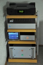
But the problem is, I haven’t more space in my Hifi Rack (see the photo).
So I tried to modify the case. It is only 230 x 280mm and there is no more space between the parts.
But now it is ready and the case is good for 4 hours music.
I will test it the next weeks and maybe make one more little changes to get a longer time before the temperature gets high. But for the next time I wanna enjoy the sound.
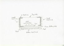
Owen it is a good idea to take the next bigger size of this case series and additionally install bigger heat sinks on the left and the right side of the case.
But be sure to integrate four L-formed heat sinks (look at my sketch) to get enough of the heat coupled to the left and right side and to the top of the case.
Owen it would be nice to get a little bit more gain in the output stage. Have you an idea how I should to it. Change the source and the drain resistors? Which values?
My Aleph-X is not very sensitive. I use the DAC between my Trinnov Optimizer ST2 Hifi and the Aleph-X amplifier. The sound comes from my BigCDPro transport.
I only use the digital signal path of the Trinnov.
It would be nice to get 3dB more, better 6 dB more gain.
If it is not possible or difficult, then I have to change the value of the input resistors of my Aleph-X. Can you simulate possible changes to get more output gain in the DAC?
Regards
Horst
thank you all for the praise!
Owen it is no problem to mount the Buffalo III Board to the first version of mainboard.
You only have to be sure that the side with the ribbon cable shows to the power supply side.
To turn the ribbon side to the input side of the mainboard is not possible, because the screw holes of the Buffalo are not symmetric. There is not much space between the ribbon cable and the capacitors of the mainboard. But it is ok.
In December I got a Buffalo III board and there was no other option than to integrate it to the mainboard, that I got from you.
With the Buffalo III board now it it easy to integrate a high quality digital volume control and you get it free with the Buffalo III.
The temperature:
Normally nobody is so crazy to squeeze such a “hot DAC” into such a little case.
But the problem is, I haven’t more space in my Hifi Rack (see the photo).
So I tried to modify the case. It is only 230 x 280mm and there is no more space between the parts.
But now it is ready and the case is good for 4 hours music.
I will test it the next weeks and maybe make one more little changes to get a longer time before the temperature gets high. But for the next time I wanna enjoy the sound.
Owen it is a good idea to take the next bigger size of this case series and additionally install bigger heat sinks on the left and the right side of the case.
But be sure to integrate four L-formed heat sinks (look at my sketch) to get enough of the heat coupled to the left and right side and to the top of the case.
Owen it would be nice to get a little bit more gain in the output stage. Have you an idea how I should to it. Change the source and the drain resistors? Which values?
My Aleph-X is not very sensitive. I use the DAC between my Trinnov Optimizer ST2 Hifi and the Aleph-X amplifier. The sound comes from my BigCDPro transport.
I only use the digital signal path of the Trinnov.
It would be nice to get 3dB more, better 6 dB more gain.
If it is not possible or difficult, then I have to change the value of the input resistors of my Aleph-X. Can you simulate possible changes to get more output gain in the DAC?
Regards
Horst
Attachments
Last edited:
Do,
........ heat sinks and chassis - the most difficult part of the build .....
Ciao,
Nic
Yes this is correct.
To dissipate the heat of this DAC design is the biggest problem.
Owen, should we think about less rail voltage?
Does it really sound bad with lower rail voltage?
If you wanna use this DAC with +- 45V for a longer time, you need a big case with big heat sinks. Also the regulaters get very hot in a closed case.
Owen, because I get no answer from you based on my inquiry about modify the output stage to get more gain, I think it is not possible. Is this correct?
Where are all the other DAC builds?
The first group buy was including 37 boards.
Hi Salomon,
It's certainly possible to get far more gain by simply increasing the resistor values for the four power resistors. Doubling the value will double the output voltage swing.
It will also halve the current through each leg, which will halve the power dissipation.
So, in short, you get twice the gain, half the power dissipation, and less performance in terms of distortion.
As for the absolute impact on sound, you'll really have to try it and decide for yourself. The results are easily measurable, but may not be audible.
Regards,
Owen
Hi Owen,
thank you for your quick response.
I think I will test it and then tell you about the sound.
Maybe this will also be a option for other builders.
67 watts are too much for me for a DAC in my little case. I hope that it is still possible to get a good performance and additional more gain changing the resistors to a higher value.
Regards,
Horst
well tbh when I saw your case I thought you were being quite optimistic, hopefully you can sort it out without too much impact on the sound, but for me the sound is good enough that I dont mind having a dac that needs this much heatsink. your case is too small for any optioned up modern dac (particularly ess) regardless of IV stage IMO (just look at what is required for the SEN jfet IV). Me i'm building 4 channel dac and its a 2 box build. in my experience it does sound slightly more constricted at lower voltages, and in my testing for matched fets the behavior of the fets at lower voltage was easy to see. YOU are free to lower the voltage, ME, not a chance.
Last edited:
Hi Qusp,
I do not wanna decrease the rail voltage, because I know that it is not good for the sound. Maybe because the FETs then are running with a very low Drain-Source voltage (only about 10V).
+- 45V is my choice too. Then the Drain-Source voltage will be about 20V - 1,7V = 18,3V
I only have to order four caddock MP930-750 Ohm. That´s all.
And then will change the drain resistor to 400 Ohm and the source resistor to 750 Ohm. So I can use the Source resistor as the Drain resistor and must not order both values.
This modification is doubling the output level and decrease the power consumption nearly to the half. The drain-source voltage stay nearly the same (only about 1V difference) as before the modification, but the current is nearly the half. Also the Gate-Source-Voltage is nearly the same (from 4,20V to 4,15V)
Because my Input resistor of the power amp is about 20 KOhm and the XLR-Cables are very short, I think it will sound good.
Owen maybe you can simulate the difference between the two versions, especially THD+N
That would be very fine. Thank you for all.
Regards,
Horst
I am ordering components from RS, can someone advise me for SMD, especially for capacitors, must I use the same package/case as specified in the BOM? For example: 1uF 100V must be 1210? Since RS has MOQ of 100 for some components. Thanks
Yes you will need same size smt package.
Is there any reason to order from rs? For us in Australia we find they have obscene markup and shipping costs and is normally better to order from mouser or digikey and pay for their international shipping.
Is there any reason to order from rs? For us in Australia we find they have obscene markup and shipping costs and is normally better to order from mouser or digikey and pay for their international shipping.
Yes you will need same size smt package.
Is there any reason to order from rs? For us in Australia we find they have obscene markup and shipping costs and is normally better to order from mouser or digikey and pay for their international shipping.
I take your advice and ordered most of the parts from digikey although it is more expensive than Australia but still cheaper than RS Hong Kong. Thanks. But I have another problem, I can't source the Pulse Transformer in Hong Kong🙁
It is only for balance input, may be I will try other brand.
Last edited:
- Home
- Source & Line
- Digital Line Level
- Build Thread - A New Take on the Classic Pass Labs D1 with an ESS Dac