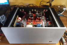
Mofo/Inpol with 195T5
bias 4A 30VDC
44W on 8ohm
40W on 4ohm
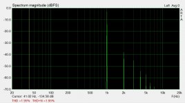
this is the maximum power to obtain a distortion with a linear decreasing of harmonic decay.
Now I am using MBR40250 diode bridge instead of previous DSA70C200HB dual diodes to eliminate a big noise problem separating the ground of each channel.
I am working on a new pcb version to correct some little problems.
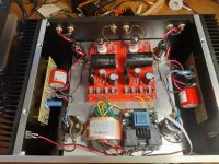
bias 4A 30VDC
44W on 8ohm
40W on 4ohm
this is the maximum power to obtain a distortion with a linear decreasing of harmonic decay.
Now I am using MBR40250 diode bridge instead of previous DSA70C200HB dual diodes to eliminate a big noise problem separating the ground of each channel.
I am working on a new pcb version to correct some little problems.
Attachments
Last edited:
Everything is in the designer article. I believe it’s around 0.2 ohm for a DF of 40.
Last edited:
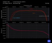
Mofo/Inpol with 195T5
2 x IRFP240 with Rg=900ohm and Rs=0.22ohm
total bias 4A 28.2VDC
about 40W on 8ohm thd about 2% with perfect decay
about 40W on 4ohm thd about 2% with perfect decay
Rout about 0.2ohm
Freq. 3.5Hz - 220KHz at -3dB on 8ohm with Cout=10000uF
Freq. 7Hz - 220KHz at -3dB on 4ohm with Cout=10000uF
Total voltage gain with my 6072A driver 26.8x = 28.6dB
Vin = 0.689Vrms -> Vout = 18.28Vrms
Attachments
Last edited:
did any ever tried a balanced "bridged" version of MoFo?
it should cancel second armonics
Why you don't like second armonic ?
I like a linear decay of armonics 🙂
I have a balanced source therefore balanced mofo seems logic
No need of output cap and chokes can be replaced by cheap ei core dual secondary transphormer
No need of output cap and chokes can be replaced by cheap ei core dual secondary transphormer
did any ever tried a balanced "bridged" version of MoFo?
it should cancel second armonics
yes, for balanced signals probably a Circlotron amp. is a good solution and you don't need the choke.
I have developed some Circlotron projects in the previous years and the result is good.
I like a linear decay of armonics 🙂
Exactly right.
Very low 2nd harmonic sounds (to me) dry and lifeless.
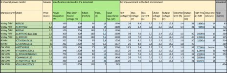
I think the best mosfet for this project are:
- IRFP150 in case of a single mosfet
Output power until 25-30W
Rout=85mohm (no Rs)
Ft=200KHz (Rg=470ohm - driven by my 6072A)
- IRFP240 for the parallel
Output power until 40-50W
Rout=200mohm (Rs=0.22ohm)
Ft=220KHz (Rg=900ohm - driven by my 6072A)
I have found many fault with HUF75639G3 and FQH44N10-F133 so I think this component are not very robust for this use especially in the parallel configuration also with high values of Rg.
Many other mosfet in the table have a good high frequency cut-off but too high Rout.
The 0.2ohm is a very good value if compared with a pure vacuum tube single ended amplifier with about 2ohm (845 with OPT 10Kohm).
Choke min 100mH for a fulll range use from 20Hz.
Attachments
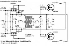
any schema of follower Circlotron? with gain = 1
yes, here you can eliminate the feedback, the interstage transformer and use interstage capacitors.
The bias voltage will be apply to one terminal of the 28K (2x56K) resistors instead of ground.
Attachments
Last edited:
Some reading for you marconi118, the second link uses SITs - should be easy enough to modify for MOSFETs.
Home | Circlotron Audio
AMPLIMOS V-Fet & SIT Amplifiers, One Stage Amplifiers
Home | Circlotron Audio
AMPLIMOS V-Fet & SIT Amplifiers, One Stage Amplifiers
I think that will fix your issue.
The Zener was upgraded to "mandatory" some time ago, but I'm afraid that info is somewhat buried in lots of other information. It is especially important when using other MOSFETs (which may have even lower maximum Vgs) or other inductors (which might have a lot more "kick")
Let us know how you fare. 🙂
I installed the zener diode and replaced Q1 . Performed bias and made sure to power off the board by cutting the power at the AC source.
It works great. It has been in the system for a few days now and the sound is very transparent and very detailed. Somewhat different than my SE EL84 tube amp.
Thanks for every ones help.🙂

- Home
- Amplifiers
- Pass Labs
- Build This MoFo!