BA-3 pre is also the preamp I will use for MoFo. I am working at the PSU in the moment and have all the parts for BA-3 pre…….apart from the attenuator.
What will I need to drive the MoFo properly?
you will have to answer two questions to yourself:
"How many volts input into Mofo do i need to get the listening volume i like out of my speakers"
"What kind of distortion would i like to add to the Mofo sound (which is rather neutral..)"
Myself i use the following 4
BA3
LuminAria
NuHybrid (Korg triode with buffer by Pete Millet) in two versions:
without step-up transformer (for high efficiency speakers and low volume)
with step-up transformer
If the preamp has not enough gain, what do you think about connecting an input transformer of 1:4 for instance. What about driving the Mosfet and the frequency response?
I am building the BA-3 pre because it has a lot of gain. It is made for power amps that has no voltage gain. In the moment I use a preamp which has max. 10 dB of gain. This is fine for MoFo with 94 dB speakers. It is only low level recordings where I am close to the 10 dB the preamp can deliver. If I want to play very loud I may need a bit more than 10 dB but I also build BA-3 because of other qualities…..
I would like to use it in biamp in high frequencies since around 300 Hz to up. Maybe I can reduce the value of the choke from 50 mH to what ?
This issue has been discussed a lot in this thread…...but can't remember the post numbers. I think the purpose was the same......as far as I remember MR also made some experiments with smaller chokes…...maybe he remember where to look back in this thread.
Hi All,
First of all a big thanks to Michael for sharing this great design. I have completed my build of the 24V version of the MoFo and I like the sound very much. Unfortunately, something went wrong this morning. I have built it with a very low priced inductor that claims to be rated at 3.0A (and I am suspecting this is the problem). It has a DCR of 1.3 ohms, so I biased it at a voltage of 3.25, i.e. 2.5A.
Anyway, it has been running for 2 weeks, and this morning while playing some music I heard a pop on the left channel, and after that no more music, leaving a low frequency hum on the speaker. The right channel is still fine. When I touched the surface of the inductor casing, it seems to be much warmer than that of the right channel. I have not started any troubleshooting / measurements yet. My questions:
1. What are the recommended steps to troubleshoot?
2. In case the inductor is found to be faulty, will this be a good replacement? https://my.element14.com/hammond/195s4/choke-70mh-15-chassis/dp/2893269?st=hammond inductor
Thanks & Best regards
Liu
An externally hosted image should be here but it was not working when we last tested it.
An externally hosted image should be here but it was not working when we last tested it.
An externally hosted image should be here but it was not working when we last tested it.
Hi Zen Mod,
Thanks for the reply. I have done the following:
1. On the faulty channel, measured the voltage across the inductor, V=9.5-11.0 increases with time, does not change much when I turn P1 anti-clockwise (many turns). Iq=6.9-8.5 A.
2. On the good channel, measured the voltage across the inductor, V=3.25, Iq= 2.5A
3. Swap the inductor or the normal channel to the faulty channel, V=9.5-11.0, same as step 1.
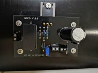
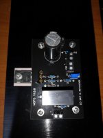
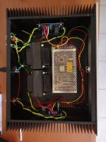
So I can now conclude that the problem does not seem to be caused by the inductor. So how should I proceed? Attached are pics of the finished chasis and the faulty channel mounted to the heatsink. Visually I can't detect any burnt component. The colour of the solder on the transistor does appear slightly charred as compared to the normal channel though. Could I have burnt the transistor?
Best regards
Liu
Last edited:
An externally hosted image should be here but it was not working when we last tested it.
An externally hosted image should be here but it was not working when we last tested it.
An externally hosted image should be here but it was not working when we last tested it.
Try again with the pics.
The Mosfet may be damaged. Did you implement the protection zener diode?
You could measure the voltage over the gate stopper resistor.
You could measure the voltage over the gate stopper resistor.
left down - button "post reply"
or left right , button "quote"
in both cases you'll have opened advanced reply window and if you scroll down , you'll see "manage attachments"
it seems you have Dodo mosfet , and it's easy to check that , but only when you are able to post pictures
or left right , button "quote"
in both cases you'll have opened advanced reply window and if you scroll down , you'll see "manage attachments"
it seems you have Dodo mosfet , and it's easy to check that , but only when you are able to post pictures
The Mosfet may be damaged. Did you implement the protection zener diode?
You could measure the voltage over the gate stopper resistor.
and it'll tell us something just in some cases ....... precisely - only when mosfet is drawing excessive gate current
just replace mosfet on bad channel and rebias
take care of proper torque and isolation to heatsink
always use BIG washer for mosfet , and always use spring washer
take care of proper torque and isolation to heatsink
always use BIG washer for mosfet , and always use spring washer
just replace mosfet on bad channel and rebias
take care of proper torque and isolation to heatsink
always use BIG washer for mosfet , and always use spring washer
Thanks Zen Mod. I will replace the Mosfet and report back.
Are you using one or two SMPS? What's the current capability of the SMPS?
Hi Vince,
I am using 1 single SMPS with current rating of 6A. Perhaps I should change it to a bigger one, coz the dimensions for 8A from the same company seems to be the same.
The Mosfet may be damaged. Did you implement the protection zener diode?
You could measure the voltage over the gate stopper resistor.
Hi Meper,
Yes. I think I did install the protection zener diode. 🙂
- Home
- Amplifiers
- Pass Labs
- Build This MoFo!