

This is looking like a plan - I have some heat sinks. I usually build with DHTs so I'd be looking to use one as a driver, like 01A, 26, 10Y.
01A Amplification factor=8x Ri=10-11Kohm
26 bAmplification factor=8.3x Ri=7300-8900ohm
10Y Amplification factor= 8x Ri=5000-6000ohm
Probably you need to choice a tube with higher amplification factor to be connected directly to the source and a lower internal resistance to load the high input cap. of the mosfet.
does the DCR of the choke influence negatively to the output impedance of the MoFo?
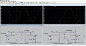
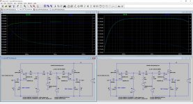
The parameters of the choke are important and there are big differences in low frequency, see here the simulations with different chokes.
100mH RDC=0.6ohm vs 100mH RDC=1.8ohm
100mH RDC=0.6ohm vs 10mH RDC=0.6ohm
10Hz, 20Hz and frequency response
Attachments

What about heatsink.....does it get hot?
Or is MOSFET "dead" before heatsink gets hot?
Maybe a picture with heatsink attached would be good?
The heatsink is very hot
The mosfet without the heatsink will die
Attached file not arrived
01A Amplification factor=8x Ri=10-11Kohm
26 bAmplification factor=8.3x Ri=7300-8900ohm
10Y Amplification factor= 8x Ri=5000-6000ohm
Probably you need to choice a tube with higher amplification factor to be connected directly to the source and a lower internal resistance to load the high input cap. of the mosfet.
Yes indeed - as above. So what amplification factor do I need here? DHTs stop at around 11 for the 4P1L but that's not my favourite DHT even if it has lower Ri at around 1.8K. I could also use 2P29L (3K) or 112A (5K). I could use a LL1660 for step-down but we're probably looking at 2 stages there, in which case the second stage would be something like a 2a3. Or something like an EL33 in triode, where we have around x20 gain and Ri around 1.2K.
Can you give me an idea of the amplification factor needed to drive the MoFo? I don't listen very loud so "just enough" to drive it properly is OK.
I have a Mofo/Inpol with a power near to 40W on 8ohm.
To get 40W on 8ohm for example you need 18Vrms.
The my voltage stage using the 6072A tube need an input signal of 0.58Vrms to give 18Vrms and the my source a DSC module is able to produce more than 1Vrms.
I plan to use the MoFO in my car...
What inductor and bias for 14V psu 4ohm load?
Any advice in a preamp that could bring the MoFo to clip with source 2Vrms from auto radio?
What inductor and bias for 14V psu 4ohm load?
Any advice in a preamp that could bring the MoFo to clip with source 2Vrms from auto radio?
Last edited:
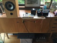
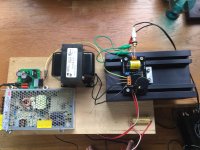
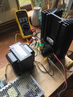
Well, after 3 years of chin scratching finally got to put the parts together for a basic test of one channel Big MoFo before building into chassis... Chassis design still in progress...! 193V inductor measures 1.1 Ohms, 24v Meanwell SMPS, Allocap CapMX. Adjusted to 26vdc output from Meanwell. Adjusted AllocapMX pot so as to read 24v at output.
Biased up reading 2.6vdc across the 193V inductor. Testing with music - reading around 54 degrees C just above the IRFP250.
Using chinese valve pre for listening test through self-constructed Bamboo Ply Tannoy DC1 clone. Amazing how so few components can sound so detailed... and... generate so much heat!
I plan to use the MoFO in my car...
What inductor and bias for 14V psu 4ohm load?
Any advice in a preamp that could bring the MoFo to clip with source 2Vrms from auto radio?
Sorry I can't help with your questions, but...That sounds insane. Insanely awesome! You have to do it and share some pics!!
I plan to use the MoFO in my car...
What inductor and bias for 14V psu 4ohm load?
Any advice in a preamp that could bring the MoFo to clip with source 2Vrms from auto radio?
So, 14V mean 14Vp - 2V about (lost on mosfet) = 12Vp => 12 / 1.41 = 8.51Vrms
Pout = 8.51 * 8.51 / 4 = 18W
Ibias = 12Vp / 4 = 3A
so you need a choke 3A with min 100mH for a full range
3A 28mH like the Hammond 159ZE for mid/high freq.
The power to dissipate will be 14V * 3A = 42W on each channel.
About the driver you can start with a normal op-amp.
[SIZE=+1]
[/SIZE]
[SIZE=+1]
[/SIZE]
why 100mH? original MoFo has 50mH for 8ohm, therefore I suppose 25mH for 4ohm?
Why screw the nice MoFo with a op-amp preamp?
Why screw the nice MoFo with a op-amp preamp?
Isn't it like crossovers?
Halve the load and halve the L to keep the frequency equal? Output capacitor should be the double
Halve the load and halve the L to keep the frequency equal? Output capacitor should be the double
sorry, my brainfart, not enough coffee in system
you're right - for lower load, lower value choke
you're right - for lower load, lower value choke
.....About the driver you can start with a normal op-amp.....
With >28V supply. Which is hard to find in a car.
The 14V supply can "work" if we rig a SE device with a plate/drain choke. It just barely works and the driver will be at least as colored as the output MoFo. So that is another design snare.
- Home
- Amplifiers
- Pass Labs
- Build This MoFo!