Hey,
Its time to scale things a little Up. A mofo with 100v/2,5a. Why? AS a fun Project in dark times. The funny thing is: it worked. Sounds quiet wonderful. I didn't measured anything, it might kill the fun in the project.
But: after some hearing, something like aleph p plus two of that m.o.a.m used as a brighted monoblock came to my mind. That may cross out the even distortions or at least lower them...
Attachments
Current source
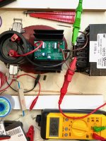
I needed a better way of measuring the DC resistance of my chokes. So with a little extra time on my hands...
The PCB is from a spare custom ACA set that I was working on a while back. The ACA current source is easily adaptable to 1.0 Amps from a 12V battery. The Mosfet is an IRFP044. From the ACA 1.6 schematic, I lowered R7 to 3.32 kΩ and set R1 through R4 for a total of 0.653 Ohms. It was also necessary to set R15 to 10k to get an actual 1.01 Amps from the current source. Output is taken between the Drain and Source connections of Q1, which is otherwise unpopulated.
Attachments
you can use diode test on your DMM as CCS
measure current of diode test with another DMM, write it down , apply diode test on choke, measure voltage across choke , divide with written current
voila!
measure current of diode test with another DMM, write it down , apply diode test on choke, measure voltage across choke , divide with written current
voila!
Sure, but that's not nearly as much fun!
😉
Aside from that, this current source has a broader range of resistance that it can measure. Especially if I switch the battery to 24V.
😉
Aside from that, this current source has a broader range of resistance that it can measure. Especially if I switch the battery to 24V.
Last edited:
has anyone played with the output cap C2? Does higher quality caps makes a big difference with this amplifier or it is not worth exploring? Right now I have the one suggested in the BoM (Nichicon UFW 25V 6800uF) but was thinking of upgrading to Mundoef M-Lytic AG MLGO
Mundorf Capacitor 6800uF 40Vdc MLytic® AG MLGO
What are your thoughts?
Do
Mundorf Capacitor 6800uF 40Vdc MLytic® AG MLGO
What are your thoughts?
Do
I am also starting with the recommended output cap, and have some other options to try as well. I have some Mundorf 68 uF RAW E-caps to try in parallel with the Nichicon KW. I also plan to try the Nichion KS series 8200 uF, 25V. It is said to be similar to the KG series that I prefer for my ACA builds.
Of course I will also be trying different Mosfets on a second set of boards. I have a few of the FQH44N10 left over from my F6 build.
Of course I will also be trying different Mosfets on a second set of boards. I have a few of the FQH44N10 left over from my F6 build.
Since we are talking about an appropriately sized coupling cap for the job, please read this -
SYclotron Audio | Why are people obsessed with coupling caps?
SYclotron Audio | Why are people obsessed with coupling caps?
Unfortunately it is not as simple as just mere measurements as many just think... I'm not talking about expensive caps, you can possible tell the difference with a simple Wima mks2 and a Panasonic metal film dipped capacitor of the same value as input cap. You can do a quad blind test and I'll always find the right one. Now, I don't know about 300$ caps, never bought never will and don't know if I would hear a difference between a good 20$ cap vs a good 300$ cap... But I definitely heard an immediate difference between the cheap mks2 and the Pana and not only me.
I'm also not the one to byte down on expensive cables either, I prefer making my own cables. Tend to stay away from snakeoil stuff for sure but I can't help noticing the effect on sound signature with different input caps. Maybe I'm just crazy, but I like it! 🙂
All the best!
Do
I'm also not the one to byte down on expensive cables either, I prefer making my own cables. Tend to stay away from snakeoil stuff for sure but I can't help noticing the effect on sound signature with different input caps. Maybe I'm just crazy, but I like it! 🙂
All the best!
Do
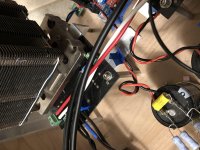
Initial bias set & burn-in
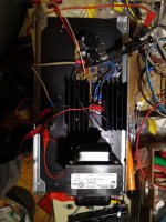
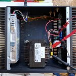
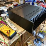
I finally got the most basic version of my MoFo wired up. This doesn't have a gain stage or a power filter / regulator. The Meanwell RSP-150 has been dialed back to 25.5 Volts. Bias current is just over 2.93 Amps. With the lid screwed on and left to soak thermally for about an hour, the side with the MoFo PCB and IRFP250 is right on the edge of being too hot to touch for more than 10 seconds. So, right about where I expected and hoped it would be. Not bad for dissipating 74.7 Watts.
The chassis is a Mini Dissipante 3U, 250 mm deep. I bolted 1/4" thick slabs of copper on both sides. The SMPS didn't need the thermal enhancement, but was easier to attach to the inside of the heatsink that way. The IRFP250 no doubt benefits from having the copper heat spreader.
Attachments
Well, the IRFP250 is 'only' dissipating 69.1 of those Watts, the big choke is getting the remainder.
Does that help?
This may be the one amp that I shut down at night to preserve the device life.
Does that help?
This may be the one amp that I shut down at night to preserve the device life.
Me Chicken
no more than 50W per T0247
40C on heatsink , then OK ...... but with more than that .......
don't use force - use bigger hammer
which means Puck with buffer in front
no more than 50W per T0247
40C on heatsink , then OK ...... but with more than that .......
don't use force - use bigger hammer
which means Puck with buffer in front
This amp can be dialed up and down considerably, especially if I include the CapMx after the SMPS. The original plan was a filtered 25 Volts at the amp boards, and 3 Amps bias. Still in excess of the usual ‘big’ MoFo running at 24V and 2.5A.
I have another pair of boards which will get the FQH44N10 instead of the IRFP250. They have better power dissipation and may be the ones I use for full power.
I have another pair of boards which will get the FQH44N10 instead of the IRFP250. They have better power dissipation and may be the ones I use for full power.
I took another look at the Mosfets and saw that the FQH44N10 does not have a thermal advantage over the IRFP250, though it has other attributes which make it a good choice for my F6. Another part I’ve been looking at is the IXTH64N10L2. This may be the “bigger hammer” that works for the MoFo. Not quite hockey puck performance, but it should be able to handle steady 70 Watt operation.
Hi TA,
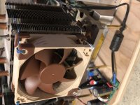
With its single output device, a High Bias MoFo is a perfect candidate for a cpu cooler/Noctua fan combo. That setup is capable of well over 120w of heat dissipation.
With its single output device, a High Bias MoFo is a perfect candidate for a cpu cooler/Noctua fan combo. That setup is capable of well over 120w of heat dissipation.
Attachments
Last edited:
There are a number of big MoFos that are continuously pushing 53.75 Watts through the IRFP250. That is assuming a 24V supply and a Hammond 193V choke. This seems to be the upper region for passive cooling. The big fan cooled heatsinks extend the working range well above the 55 Watt mark.
I’m interested in pushing the boundary of what can be achieved without resorting to a CPU cooler. This is partly because I want to eventually add a tube gain stage on the top plate of my case. Maybe that’s just me being my FAB self. 😉 I prefer the look of some nice transformers and large glass tubes to a block of thin metal fins. I can also try a small fan inside the case. Even a little airflow makes a big difference.
This is also an ongoing experiment in power dissipation. I’m gathering data for the next big amp build or two.
I just did another thermal soak with different settings for the power. The SMPS voltage was increased to 26.0 Volts, and the quiescent current was lowered to 2.4 Amps. No other changes were made. This results in 60 Watts being dissipated through the IRFP250.
The thermal performance is much better and in line with my other FW clone amps. The heatsink is fairly warm to the touch, but not hot. I don't notice any hotspots, and can leave my hands in contact with the area closest to the Mosfet indefinitely. Bias current reaches a stable value within 15 minutes, and the heatsinks reach their thermal equilibrium after about a half hour.
This lower power dissipation seems to be much better managed. The thermal performance of the 3U x 250 mm heatsink looks to be confirmed at 0.41 °C/W. Given that the 60W is being dissipated by a single device, use of a copper heat spreader is advised.
I will use this as the baseline power setting for the remainder of my exploration with the MoFo. I need to determine if the SMPS is sufficient by itself (as many here have done), or if it needs help from a larger reservoir capacitor. There are different options being considered for a gain stage. Several forum members have been helpful in suggesting alternatives. I will select one of the tube preamps and have a custom acrylic top cover made to hold that as a self contained assembly. In the meantime, I will also work with Juma's Gyrator loaded Son of ZV9 as a solid state gain stage.
Attachments
I used my MoFo version for several month with 26 VDC supply and 3A bias. Heatsink went to about 55 C but never had a problem. I had 4A F fuses at PSUs output just in case (dual mono design). I had a "stupid" accident where both channel fuses burned with a very visible flash from fuses but no other damage. So the worst thing that can happen is that you will burn IRFP250. I think the probability is quite low even with 55 C on heatsink. So you could take it as a calculated risk…...and continue with high bias until…..and if it happens then decrease bias a bit.
Now M2X has been kind of permanent for at long time so MoFo will be cut into pieces and be placed "on the shelf"...as components …..want some 20 kg chokes? 🙂
Now M2X has been kind of permanent for at long time so MoFo will be cut into pieces and be placed "on the shelf"...as components …..want some 20 kg chokes? 🙂
- Home
- Amplifiers
- Pass Labs
- Build This MoFo!