tubesguy, I don't know much, but IRFP150 is less expensive.
Looking at the specifications:
IRFP150:
Vdss 100V
Id 42A
PowerMax 160W
IRFP250:
Vdss 200V
Id 30A
PowerMax 214W
Looking at the specifications:
IRFP150:
Vdss 100V
Id 42A
PowerMax 160W
IRFP250:
Vdss 200V
Id 30A
PowerMax 214W
Silly question
What about using this topology for a preamp? A cheap luminaria?
Preamp? You'd get buffer, with no voltage gain. B1 is an excellent buffer already. I don't see a point...
Nice. Why the 150 rather than the 250?
There are some differences on mosfet specifications from one manufacturer to another, a low input capacity is crucial for having a good high frequency response:
- IRFP150 IRF Ciss=2800pF
- IRFP150 Fairchild Ciss=2000pF
- IRFP150 Vishay Cis=2800pF
- IRFP150NPBF Ciss=1900pF
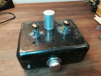
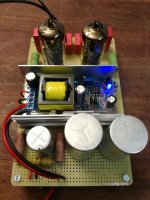
Very nice Tony! So compact.
What chokes are those?
same dimensions as the 193v, 1.5inch center leg stacked to 2 inches, 500 turns of #18 wire, gapped and about 750 mH....
3 Preamps for Mofo
About a year ago i started looking into alternativ preamps for Mofo
Requirement was a voltage gain of 30x.
After a year of trying and building i kept the following three
First one is Andrea Ciuffolis preamp for his power follower.
A very nice preamp and you can buy the complete circuit boards (pre and power amp!). They are cheap and of excellent quality. Details can be found on
the Power Folllower.
Second preamp uses a IF860 tube (or IL861) directly coupled to a mosfet follower
The tube heaters are directly fed by the Mofo powersupply
B+ is generated by a hvflyback generator
Number three uses the same tubes without buffer
The power supply uses a chinese hvflyback for B+
Below are some pictures of the build and schematic
Details and measurements are in the next post as attachment
Attachments
I have the power follower 2019 tube frontend boards, but will try something a little simpler first with 30db gain.
Here is the attachment mentioned in the previous post
How many output voltage and gain you need ?
I can optimize the circuit with other parameters.
Here is the attachment mentioned in the previous post
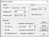
Please add on Arta software the THD display
Attachments
Last edited:
Thank you for your proposal and the hint regarding THD. I am not very familiar with ARTA i rather use REW. Sorry for having forgotten THD.
But it is not very important here since we just have a look at what we get from different preamps that work under the same conditions.
For my Mofo i do not need more than 8Vrms
I went to 14Vrms in the measurements just to give an idea of how they behave in this region.
By the way the IF860 at 30Vrms only reaches 1%THD
Hello, my source gives a balanced 3V. Can the MoFo drive some actively crossed, 16ohm compression drivers?
Concerning driving compression drivers with the MOFO ...
I have a pair of the HAMMOND 195T5s on hand so I will use those with 24 volts supply. Of course I am tempted to get the LUNDAHL 2733s but will get it built with these monsters first. For the last decade they have been used as weights.
Earlier someone had used +- 12 volts supplies which I find worth considering. If one is willing to go to the trouble is there any real advantage to this? Seems like it could be good keeping the signal ground out of the power supply.
I want to use this amplifier from 500 Hz to 7kHz.
I would like to use either, or both, of the capacitors to effect a high pass crossover. I have found it better to crossover over at the amplifier and not use the crossover in the XILICA for this channel.
Can one lower either one without messing it up? With SIT1s I use the caps as my crossover and would like to do the same thing here. Seems awkward following 6800 uF of capacitance with another 35 uF capacitor. With the SIT1 there is just that capacitor and instead of 5 uF at the input I use just under 1 uF. Can I do this with the MOFO?
I want to use the SIT1s with the VIAWAVE ribbons. Or it could turn out to be the other way 'round. I get the feeling the MOFO and the compression drivers will be very compatible and the fact that both amplifiers are pure single ended should make for a cohesive sound. I like big sound!
This driver and horn is very efficient - I am using a XILICA XP2040 on each channel to separate things. This has a specified output impedance of 50R balanced and 7 output volts.
I do not think I need much gain but then I do not want to have to run the XILICA level up too high. The idea of an input transformer looks like the easy way - I would like to use the balanced output and get some gain - seems like 1:4 would be more than plenty and I do not think the XILICA would have much trouble driving it. 1:2 would probably be just fine - 6 dB should be plenty. With the reasonable cost of the EDCORs one should just get both.
I have looked at the M2 input circuit - I have plenty of the FETs - this looks like it could be easily converted to balanced input - but I have no real idea - would disconnecting the 2SJ74 from ground and connecting it to the negative lead give a balanced input? I like the simplicity of just a transformer but I know things can be too simple.
Since I recognize the fact that I am an electronics dilettante I am hoping to get some advice.
(ZM are you around?)

just pulling your leg , of course 🙂
yes for smaller cap on output , you did it already before
besides smaller cap, you can also decrease choke inductance
fro cap , you know that magic numbers are F=1/(2*Pi*R*C) , so it's easy to calc your cap for desired F3
same with inductor , first calc from back of my skull is Xl=2*Pi*F*L
vary capacitance from calculated to your liking , while keep inductance larger - at least octave down from frequency of interest
for xformer - having Bal in for your needs , SE out for MoFo ........ primary needs to have CT , so upper end of primary is (say) positive end , lower end of primary is negative end , CT goes to gnd
of course , one can skip CT , but it's easier this way ......
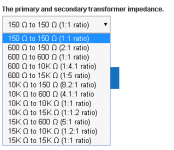
M2's original xformer is 600:15K (nominally) , resulting in (15K/600)^-2 voltage ratio , which is 5V/V = smidge bellow 14db
if that's too much for your needs, go to Edcor's and choose lower ratio ...... but!
see enclosed ;
whatever you choose , driven in right way or rotated and driven "backwards" , sole adequate one with lower gain is 600:10K (nominally) , giving 4V/V , aroundish 12db
for instance , if you wish 6db , 2V/V - you can theoreticaly use 600:150 (nominally) , rotated so driven at "150"side ...... but there will be probably lack of inductance that way , taking in account transposed Rin of Mofo .......... on the other hand , maybe that's doable, simply because you don't need low end ....... so , maybe that one is worth trying , if 6db is goal , even if on first look it was not adequate 🙂
you'll need separate buffer for each input leg , meaning separate buffer for positive and separate buffer for negative side of primary
yes for smaller cap on output , you did it already before
besides smaller cap, you can also decrease choke inductance
fro cap , you know that magic numbers are F=1/(2*Pi*R*C) , so it's easy to calc your cap for desired F3
same with inductor , first calc from back of my skull is Xl=2*Pi*F*L
vary capacitance from calculated to your liking , while keep inductance larger - at least octave down from frequency of interest
for xformer - having Bal in for your needs , SE out for MoFo ........ primary needs to have CT , so upper end of primary is (say) positive end , lower end of primary is negative end , CT goes to gnd
of course , one can skip CT , but it's easier this way ......
M2's original xformer is 600:15K (nominally) , resulting in (15K/600)^-2 voltage ratio , which is 5V/V = smidge bellow 14db
if that's too much for your needs, go to Edcor's and choose lower ratio ...... but!
see enclosed ;
whatever you choose , driven in right way or rotated and driven "backwards" , sole adequate one with lower gain is 600:10K (nominally) , giving 4V/V , aroundish 12db
for instance , if you wish 6db , 2V/V - you can theoreticaly use 600:150 (nominally) , rotated so driven at "150"side ...... but there will be probably lack of inductance that way , taking in account transposed Rin of Mofo .......... on the other hand , maybe that's doable, simply because you don't need low end ....... so , maybe that one is worth trying , if 6db is goal , even if on first look it was not adequate 🙂
you'll need separate buffer for each input leg , meaning separate buffer for positive and separate buffer for negative side of primary
Attachments
Last edited:
- Home
- Amplifiers
- Pass Labs
- Build This MoFo!