Have you been able to keep the bass and treble adjustment? I'd be happy if you could provide a wiring diagram for this kit in the V4A.
Hello Depaj
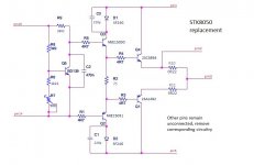
I tried to draw, what I think you did.
- It looks like you added emitter resistors 0.22 ohms
- It looks like you removed all components connected to pins 6-13 and pin 15
- It looks like you also removed the capacitor between pin 14 and 16
Am I right?
What's the setting of you potentiometer?
I tried to draw, what I think you did.
- It looks like you added emitter resistors 0.22 ohms
- It looks like you removed all components connected to pins 6-13 and pin 15
- It looks like you also removed the capacitor between pin 14 and 16
Am I right?
What's the setting of you potentiometer?
Attachments
Sorry Chregu, I didn't see your last post. Yes I was able to keep the tone controls without any modifications.
That looks about right yes.
Those are all the components used in the synchro bias circuit so they aren't needed any longer.
The kit doesn't have any emitter resistors as the sx-780 has them on the main board, I added them on the kit but you can just as well put them on the main PCB.
You can keep TP302 and 307 to connect your meter for bias adjustment.
I removed the cap on the main pcb because c2 on the kit has the same purpose (it won't harm if you leave it though).
I don't really remember where the pot was set in the end but if I remember correctly I started fully counter clockwise and went step by step from there. You can always do a test with your dim bulb connected, if the bias is to high that should limit things, you can do your tests with it connected but be sure to remove before final adjustments.
Good luck 🙂
Hi everybody, sorry for barging in 🙂.
I bought a Technics SU-V4A a while ago (actually my step into these kinds of equipments). Ever since then I've been studying more about this era and obviously started to worry about the STK8050 ICs and how long they might last.
Yesterday I've been looking inside a bit through the top grills and noticed that those ICs are not really present, and that some work has been done in that area. I opened up the amp today and they have indeed been replaced with something else.
Now, I'm not an electrical engineer at all, far from it (just sort of tech savvy). But this is what I found (doesn't look very pretty), and I want to share it with you guys, maybe it's going to help someone. Parts are <<SANKEN B1647 & D2560>>.
BTW: Does anybody know anything about the setup I have there? Is it good? Is it bad 🙄?
Attachments
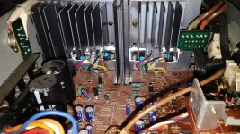
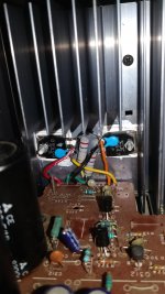

This looks like a low-cost solution but probably some kind of works too. There seem to be only 2 power transistors per channel with added emitter resistors. There's also no possability to set bias current. The other components around the STK have been removed.
Thanks. One more question if I may, do you happen to know how much power these might be putting out?
https://www.semicon.sanken-ele.co.jp/sk_content/2sb1647_ds_en.pdf
https://www.semicon.sanken-ele.co.jp/sk_content/2sd2560_ds_en.pdf
Not sure if these are the exact specsheets but it's the closest thing I found. It says they consume 130W. Does it sound resonable to assume that they will have a slightly higher output power than the old STKs, maybe closer to 80-90W?
Thanks again.
They will only "put out" whatever power is available to them. The power rating is that they can handle 130W at 25c. They should be adequately rated
Note that those are power darlingtons so they include driver transistors, nice simple solution
but I'm not sure if the 130W rating is enough in this amp say for driving 4 ohm loads.
Something is needed to bias the outputs with thermal compensation.
Nice to see you all keeping these amps working!
but I'm not sure if the 130W rating is enough in this amp say for driving 4 ohm loads.
Something is needed to bias the outputs with thermal compensation.
Nice to see you all keeping these amps working!
Last edited:
Sorry Chregu, I didn't see your last post. Yes I was able to keep the tone controls without any modifications.
That looks about right yes.
Those are all the components used in the synchro bias circuit so they aren't needed any longer.
The kit doesn't have any emitter resistors as the sx-780 has them on the main board, I added them on the kit but you can just as well put them on the main PCB.
You can keep TP302 and 307 to connect your meter for bias adjustment.
I removed the cap on the main pcb because c2 on the kit has the same purpose (it won't harm if you leave it though).
I don't really remember where the pot was set in the end but if I remember correctly I started fully counter clockwise and went step by step from there. You can always do a test with your dim bulb connected, if the bias is to high that should limit things, you can do your tests with it connected but be sure to remove before final adjustments.
Good luck 🙂
Hi, what resistors to go down from 48v to 40v. Thank you
I can really recommand using the kit we were talking about earlier in this thread, it worked absolutely perfectly on my SU-V4. You'll have to drill 2 extra holes on each side to mount to the heatsink, remove all the components related to the synchro bias circuit (I can give you the references if needed) and wire it up to the board.
Hi Depaj,
Can you make a detailed instructional post from start to finish on how to mod the SU-V4 as I have a couple of them I'd like to get working and I am sure others would like to know as well.
If you can include in there the references for any components that need to be changed/removed that would be good.
If you can add photos to show the steps that would be even better!
Hi Studio1,
I don't have these amps any longer but I will try to be as precise as possible from my notes and pictures to give you a detailed guide.
-First you will want to remove all the parts on both channels that are used in the synchro bias circuit for the original STKs :
After first step is completed it should look like this :

-Building the kit is quite straightforward if you have the instructions included.
I added the fuses to the wires for the + and - rails (covered with heatshrink on the pictures). You'll also have to add two 0.22ohm (5W) on each board, they can also be added on the main board but I found it to be easier this way.

 .
.
-Last but not least will be the wiring. The wholes are quite small so don't go with too big wires.
Going left to right when facing the module (emitter resistor on the bottom side) connect as follows :
I don't have these amps any longer but I will try to be as precise as possible from my notes and pictures to give you a detailed guide.
-First you will want to remove all the parts on both channels that are used in the synchro bias circuit for the original STKs :
- Left channel : R343, R337, R367, D303, D305,D307, D309, R339, R365, C319, C321, R375, C307, TH301, R369, R345.
- Right channel : R344, R338, R368, D304, D306,D308,D310, R340, R366, C320, C322, R376, C308, TH302, R370, R346.
After first step is completed it should look like this :
-Building the kit is quite straightforward if you have the instructions included.
I added the fuses to the wires for the + and - rails (covered with heatshrink on the pictures). You'll also have to add two 0.22ohm (5W) on each board, they can also be added on the main board but I found it to be easier this way.
.-Last but not least will be the wiring. The wholes are quite small so don't go with too big wires.
Going left to right when facing the module (emitter resistor on the bottom side) connect as follows :
- Left channel : first wire goes to where pin 16 of the stk used to be but you can also connect it to the (-) of C307 that was removed.
Second wire goes to the -48V (originally pin 5).
Third wire will be your output (pin 3). Be sure to connect this where the 2 emitter resistors meet on the module I don't have a picture of the underside of the board but if you post on when you're done it'll be easy to say if it's ok or not.
Fourth wire is the output monitoring for the overload and protection circuit, this must be connected to one side of either one or the other emitter resistor (this way third and fourth wire are connected across one of the two emitter resistors and you'll be able to use TP301 and TP303 to adjust bias). It then goes to Pin 2 on the main board.
Fifth wire is your +48V rail (Pin 1).
Finally the last wire goes either to pin 14 or the positive side of where C307 used to be (according to how you connected the first wire). - Same for the right channel except it will be TP302 and TP304. You can leave the pins for the test points in place, twist the wires around and solder so you have something to connect your voltmeter to when setting bias.

 .
.
I hope this is clear, I'm doing it from memory so it might not be, don't hesitate to ask if you have doubts 🙂.
Hi, what resistors to go down from 48v to 40v. Thank you
Why do you want to drop the voltage ?
You can't just add resistors on the rails because the more current you will draw when increasing bias or volume, the more the resistors will drop voltage.
Why do you want to drop the voltage ?
You can't just add resistors on the rails because the more current you will draw when increasing bias or volume, the more the resistors will drop voltage.
Thanks for answering Depaj. I thought you had put resistance on the marked wires, but I see that they are fuses. Thanks for your input, now I can resurrect my old V4.
One question, how is the rest current adjustment? Thank you.
An externally hosted image should be here but it was not working when we last tested it.
Thanks for answering Depaj. I thought you had put resistance on the marked wires, but I see that they are fuses. Thanks for your input, now I can resurrect my old V4.
One question, how is the rest current adjustment? Thank you.
Thanks for answering Depaj. I thought you had put resistance on the marked wires, but I see that they are fuses. Thanks for your input, now I can resurrect my old V4.
One question, how is the rest current adjustment? Thank you.
I set the bias at 7mV across one emitter resistor as advised in the description of the module kit.
I set the bias at 7mV across one emitter resistor as advised in the description of the module kit.
Thanks for your information, I hope to receive PCBs soon, and do the assembly. regards
I hope this is clear, I'm doing it from memory so it might not be, don't hesitate to ask if you have doubts 🙂.
Thanks indeed - it looks pretty clear to me.
Your efforts will help others as well, and assist people to keep these nice amps functioning a bit longer!
It may be a while before I can get to the units I have but I will certainly check back when I start on them.
- Home
- Amplifiers
- Solid State
- Build STK8050 equivalent