Hey all, this is an amazing thread and I'm in the process of restoring a mint Technics SU-V4. I have read all of the posts here, and the posts over at Audiokarma and am still a little confused. I've built my STK-0050s and installed per the threads, but am undecided about what, if anything, I need to remove from the SU-V4 board. Depaj recommends removing a bunch of components related to the bias circuitry, but I've also seen some posts saying that nothing needs to be removed. Any consensus on what needs to be removed for a SU-V4. Thanks!!
Hey all, this is an amazing thread and I'm in the process of restoring a mint Technics SU-V4. I have read all of the posts here, and the posts over at Audiokarma and am still a little confused. I've built my STK-0050s and installed per the threads, but am undecided about what, if anything, I need to remove from the SU-V4 board. Depaj recommends removing a bunch of components related to the bias circuitry, but I've also seen some posts saying that nothing needs to be removed. Any consensus on what needs to be removed for a SU-V4. Thanks!!
Using STK-0050s in Technics SU-V4, no need to remove any parts from the board, you just connect the STK-0050 to the right pins on the board, you need the extra output emitters resistors connect together.
Thanks. I made my board per the pictures in the thread with the emitters on the pcb at holes 3,5 and 6,8. I then jumpered holes 7,8 together and 3,4,5 together to complete the circuit. I've installed and tested on a dim bulb, but my voltages on the stk pins are way off. Rails are good but i have rail voltage at other pins as well. more likely problem with my stk or with rest of amp?
Please show your board picture(or your STK schematic), it is a little bit hard to read it in the thread.
I made my board per the pictures in the thread with the emitters on the pcb at holes 3,5 and 6,8. I then jumpered holes 7,8 together and 3,4,5 together to complete the circuit. I've installed and tested on a dim bulb, but my voltages on the stk pins are way off. Rails are good but i have rail voltage at other pins as well. more likely problem with my stk or with rest of amp?
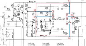
You connect the STK as below diagram, connect your STK pin number to old IC pin number(pin to pin), your emitters on the pcb at holes 3,5 and 6,8. you join 5,6 and connect to the board old IC pin3(output), STK pin 8 to old IC pin 2, you can count your STK board connected total 6 pins(other pins no need connect them) to the old IC on the board.
Attachments

I'd like to try this project on an SU-V4. For the replacement modules, am I reading it correctly that I don't need all the components I would need if this were an SX-780 restore?
Or do I build them as normal (but add emitter resistors) and remove original components from the amp?
Or do I build them as normal (but add emitter resistors) and remove original components from the amp?
Last edited:
Resurrecting this old thread. I have an SU-V4 that has been in storage the last 15 years or so after a replaced STK 8050 chip went bad.
I looked around for years for a solution for it as it’s got some sentimental value. Anyway I was excited to find this thread and the one over at Audiokarma.
I bought the amp kit from the fellow in Canada who I think designed it.
I’ve built it and is now ready to put it in the amp. My question is has anyone successfully repaired one of these Technics amp without removing any of the original components used by the old chip amp, namely the synchro bias components.
I have recently and successfully restored my SU-V4 using the Canadian modules.
My approach was to remove the minimum of components to isolate redundant circuitry.
Components removed:
Left channel - R343 R345 R365 R369 C307 (either R365 or R369 could remain)
Right channel - R344 R346 R366 R370 C308 (either R366 or R370 could remain)
Very happy with the result.
My approach was to remove the minimum of components to isolate redundant circuitry.
Components removed:
Left channel - R343 R345 R365 R369 C307 (either R365 or R369 could remain)
Right channel - R344 R346 R366 R370 C308 (either R366 or R370 could remain)
Very happy with the result.
I also successfully restored my SU-V4a, using the given schematic.
But I redesigned the PCB layout.
So here my contribution:
schematic:

PCB-Layout, transistors mounted on the backside, blue= tracks toplayer red=bottom layer

R6 = 75R (placed here two 150R in parallel)


Holes are provided to allow the bolt head and screwdriver to pass through.
Foreseen M3 screw taps...
Used then an empty PCB, and placed dots, where the transistor leads should be bent.
Then fixing the transistors on the heatsink, and placing pcb on top, that was the most tricky part, to get all leads through at once.

First I used TTA004B & TTC004B transistors as predriver, that was not working, it believe the hfe factor wasn't high enough of those transistors.
MJE15030 & MJE15031 works fine, but must be fixed isolated on the heatsink using mica plate.
Final result:

In attachment the gerber file. This layout is more compact.
I spend a lot of hours working on this project, however I'm happy with the result.
Bart
Belgium
But I redesigned the PCB layout.
So here my contribution:
schematic:
PCB-Layout, transistors mounted on the backside, blue= tracks toplayer red=bottom layer
R6 = 75R (placed here two 150R in parallel)
Holes are provided to allow the bolt head and screwdriver to pass through.
Foreseen M3 screw taps...
Used then an empty PCB, and placed dots, where the transistor leads should be bent.
Then fixing the transistors on the heatsink, and placing pcb on top, that was the most tricky part, to get all leads through at once.
First I used TTA004B & TTC004B transistors as predriver, that was not working, it believe the hfe factor wasn't high enough of those transistors.
MJE15030 & MJE15031 works fine, but must be fixed isolated on the heatsink using mica plate.
Final result:
In attachment the gerber file. This layout is more compact.
I spend a lot of hours working on this project, however I'm happy with the result.
Bart
Belgium
Attachments

I have the same problem with STK8050. Found this excellent article and I decide to build replacement.
Kindy asking for file type (PCB) which is possible to open in EasyEDA sw.
Regards
Kindy asking for file type (PCB) which is possible to open in EasyEDA sw.
Regards
Hello,
Thank you for all those amazing information!
I'm on a process to restore my Technics SU-V4A, unfortunately one channel died... I bought everything needed for the mod from PeeWee10.
I just have one question, how can i calibrate it?
Thanks
Thank you for all those amazing information!
I'm on a process to restore my Technics SU-V4A, unfortunately one channel died... I bought everything needed for the mod from PeeWee10.
I just have one question, how can i calibrate it?
Thanks
Similar to a STK-0050, measure across both emitter resistors, ~75mA * 2(Re) = 0.075 * (2 * 0.22 ohm) = 33mV
hello, I found the discussion interesting having the same problem of the lack of the STK8050.
I wanted to ask you about adjusting the Bias which ends go to the terminals of the tester of your circuit?
Are the clamp and bias trimmers on the SU-V4 board active and adjustable as per the service manual? 0.5mV clamp, 15mV bias?
i downloaded the gerber file thanks
I wanted to ask you about adjusting the Bias which ends go to the terminals of the tester of your circuit?
Are the clamp and bias trimmers on the SU-V4 board active and adjustable as per the service manual? 0.5mV clamp, 15mV bias?
i downloaded the gerber file thanks
ciao ti volevo chiedere se per caso hai comprato il pcb e installato il blocco sul SU-V4, ho scritto un post anchio perchè i dubbi erano come regolare il Bias e se vanno tolti componenti una volta montato il nuovo blocco.Hello,
Thank you for all those amazing information!
I'm on a process to restore my Technics SU-V4A, unfortunately one channel died... I bought everything needed for the mod from PeeWee10.
I just have one question, how can i calibrate it?
Thanks
Not entirely satisfied with other DIY solutions found here and on other forums, I've routed my version of the STK8050.
It's almost plug and play:
No extra drilling, needs the output transistors isolating when mounting which is a small annoyance.
Electrically compatible: Although it's necessary to go through the Vclamp and Icq adjustments, the trimmers will set to positions similar to those seen with original hybrids.
Thickness is slightly less than original component, still it can be mounted with the original mounting tab that will bend a little because it rests on the heatsink first.
I have a few spare PCB's.
I have the Gerbers but I'm waiting to sell a few modules to cover the time investment and first PCB / components order before sharing them.
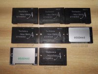
ok grazie, ho ancora un SU-V4 da riparare, 8 pezzi di moduli nuovi che funzionano ma non regolano il clamp e il bias, infatti funzionano ma dopo pochi minuti si apre la protezione perché sono finti.
PS: peccato che le fotografie siano sfocate, aspetto comunque, se i vostri moduli funzionano risolveranno non pochi problemi a molti possessori di questo amplificatore.
PS: peccato che le fotografie siano sfocate, aspetto comunque, se i vostri moduli funzionano risolveranno non pochi problemi a molti possessori di questo amplificatore.
Attachments
 English please.
Translation said:ok thanks, I still have an SU-V4 to repair, 8 pieces of new modules that work but don't adjust the clamp and bias, in fact they work but after a few minutes the protection opens because they are fake.
PS: it's a shame that the photographs are blurry, I'll wait anyway, if your modules work they will solve quite a few problems for many owners of this amplifier.
- Home
- Amplifiers
- Solid State
- Build STK8050 equivalent