ok thanks, I still have an SU-V4 to repair, 8 pieces of new modules that work but don't adjust the clamp and bias, in fact they work but after a few minutes the protection opens because they are fake.
PS: it's a shame that the photographs are blurry, I'll wait anyway, if your modules work they will solve quite a few problems for many owners of this amplifier.
PS: it's a shame that the photographs are blurry, I'll wait anyway, if your modules work they will solve quite a few problems for many owners of this amplifier.
So your new fake modules work but not as intended? When the protection relay opens is that because the modules have self-destructed?
That's my experience with the Chinese modules but I've recently been told that there are some around that work correctly, I'd be glad to know which ones...
My DIY substitute has been satisfactory for my needs so far, schematic is almost identical to original STK8050.
I've since added a few pF, because I noticed some high frequency oscillations when testing, funnily these were not high in amplitude and only occurred with the amplifier's case open.
It works well, I've repaired 3 amplifiers (6 modules) so far and they've adjusted no worries and proven thermally stable. The couple of points that could be improved are a little more copper surface on first stage PNP transistor that runs a little hot, also the SMD Emitter resistors run hot when the amplifier is at full power on 4 Ohms load.
If I redesign one day I may try for an IMS version.
some modules that I bought like the ones in the photograph cause the voltages on pins 12/13/14/15/16 to be off and do not allow you to adjust the clamp and bias, the amplifier works but after a few minutes the protection opens.
the only STK8050 power packs that are original and compatible must have curves on pins 1-2 and 15/16, unlike pins 3 to 14. You can see from this photograph the one at the top called ALT is original Sanyo and you can see the curved pins , the one below is a replica and the pins are all curved the same.
the only STK8050 power packs that are original and compatible must have curves on pins 1-2 and 15/16, unlike pins 3 to 14. You can see from this photograph the one at the top called ALT is original Sanyo and you can see the curved pins , the one below is a replica and the pins are all curved the same.
Attachments


I recently got hold of a SU-V2 to repair, one of the STK8040 was toast. The other still kicking, I was curious enough to make a few comparative measurements.
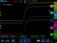
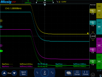
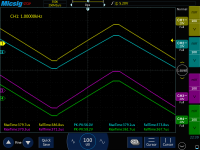
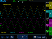
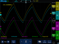
Measurements are taken with both channels loaded at 6.5 Ohm. To be as fair as possible clamp voltage and quiescent current had previously been trimmed to specification on both channels. Amplifier's voltage selector is at 240V.
It's a very close match, the clone looks a little better for VCEsat than the original, other than that they're hard to tell apart.
CH1: Original STK8040 input at pin 16.
CH2: Original STK8040 output at pin 3.
CH3: Clone module input at pin 16.
CH4: Clone module output at pin3.
Attachments
Good evening to the whole group; thanks for the answer (i hope!). I'll go straight to the question: is there a final design (or a PCB to purchase) for this Update? Thanks in advance. (Obviously I also have the same problem to solve)
Hello,
I'm trying to sell my edition in various pre assembled flavours on the big french advert website:
https://www.leboncoin.fr/ad/photo_audio_video/2453854342
Plenty of views though no one has bought any yet.
I'm not selling on eBay due to their fascist terms of use and it looks as if I'll soon quit "Leboncoin" too for the same reasons...
If you need cheap, are
confident with SMT and just need a PCB or two and the parts list I can send to Italy, I'll have to check the production and postage costs though.
I also have a spare original STK8040 to sell as when I repair these amps I'll fit two of my substitutes for the sake of symmetry.
Hello SDS,
I understand the problem with some restrictions on these sites; Can I ask you the price of the STK, or do we have to go into private conversation for these details? I don't want to violate the group rules. You confirm that your STK has pins 1-2 and 15-16 as per original?
I understand the problem with some restrictions on these sites; Can I ask you the price of the STK, or do we have to go into private conversation for these details? I don't want to violate the group rules. You confirm that your STK has pins 1-2 and 15-16 as per original?
Bart, can you share info about which components should be removed, on left and right channel?I also successfully restored my SU-V4a, using the given schematic.
But I redesigned the PCB layout.
So here my contribution:
schematic:
View attachment 1065186
PCB-Layout, transistors mounted on the backside, blue= tracks toplayer red=bottom layer
View attachment 1065187
R6 = 75R (placed here two 150R in parallel)
View attachment 1065188View attachment 1065189
Holes are provided to allow the bolt head and screwdriver to pass through.
Foreseen M3 screw taps...
Used then an empty PCB, and placed dots, where the transistor leads should be bent.
Then fixing the transistors on the heatsink, and placing pcb on top, that was the most tricky part, to get all leads through at once.
View attachment 1065193
First I used TTA004B & TTC004B transistors as predriver, that was not working, it believe the hfe factor wasn't high enough of those transistors.
MJE15030 & MJE15031 works fine, but must be fixed isolated on the heatsink using mica plate.
Final result:
View attachment 1065194
In attachment the gerber file. This layout is more compact.
I spend a lot of hours working on this project, however I'm happy with the result.
Bart
Belgium
- Home
- Amplifiers
- Solid State
- Build STK8050 equivalent