Hi everyone,
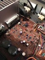
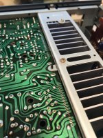
Based on the results and feedback from Depaj, I've decided to replace the STK8040s in my SU-V2 with the remanufactured discrete modules. Only 1 channel is dead, but because these modules inevitably die from heat, I've decided to replace both. I'm also doing a complete recap of the unit. I've attached some pictures of my progress so far.
The replacement modules and mounting plates have been ordered. I'll be making a large Mouser order tonight for all the components and replacement capacitors.
I'm also in the process of identifying all the synchro bias circuitry which will need to be removed. I assume they parts and locations will be similar to the SU-V4, but I'll need to trace and confirm with the service manual.
More to come,
Chris
Attachments
Hi,
Good luck with your restoration, if I remember correctly I used these :
0251005.MXL Littelfuse | Mouser France
Good luck with your restoration, if I remember correctly I used these :
0251005.MXL Littelfuse | Mouser France
Hi,
Good luck with your restoration, if I remember correctly I used these :
0251005.MXL Littelfuse | Mouser France
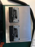
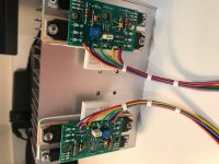
Hi Depaj, really good to hear from you. For the SU-V2, is it necessary to remove the synchro-bias circuitry? rcs16 from AudioKarma said it was not. I wanted to get your opinion directly.
Here is a picture of my completed and mounted modules.
Kind regards,
Chris
Attachments

Looks great!
If the circuit is anything like the su-v4 which i believe it is I don't see how it can work with it as you already have your bias circuit included in on the module.
I'll check the schematic tomorrow and see what I come up with.
If the circuit is anything like the su-v4 which i believe it is I don't see how it can work with it as you already have your bias circuit included in on the module.
I'll check the schematic tomorrow and see what I come up with.
Looks great!
If the circuit is anything like the su-v4 which i believe it is I don't see how it can work with it as you already have your bias circuit included in on the module.
I'll check the schematic tomorrow and see what I come up with.
I really appreciate your help Depaj. Looking forward to your response!
Right now, I have:
STK-8040-(pin 16)(left in channel) - orange
STK-8040-(pin 14)(left out channel) - purple
STK-8040-(pin 1)(+42V) - red
STK-8040-(pin 5)(-42V) - black
STK-8040-(pin 3)(output) - green
STK-8040-(pin 2)(emitter 1) - blue
STK-8040-(pin 4)(emitter 2) - yellow
I'm trying to map these to the appropriate points in the existing amplifier PCB. With the assumption that the synchro-bias circuit is removed, I assume it becomes easier. I'm trying to mark out components to be eliminated.
Kind regards,
Chris
Last edited:
Your pinout is correct.
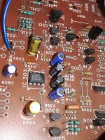
From what I see the circuit is exactly the same as the SU-V4. You can actually leave the components in there because they don't connect to anything that will be used by the new modules (except R361, R363 and R367) but I find it to be cleaner with them removed and it eliminates the possibility of connecting things wrong (that's just my opinion).
If you want to remove them here's the list for the left channel (R333, R335, C313, C315, R367, R363, R361, R355, R331, C335, C333, D303, D305, D307, D309, TH301, R371).
I don't now how much experience you have with this but I suggest you power the amp up with a dim bulb in case something is wrong.
If you decide to leave the components in maybe disconnect R333 and R335 (R334 and R336 on the right channel) from the power rails.
I really appreciate your help Depaj. Looking forward to your response!
Right now, I have:
STK-8040-(pin 16)(left in channel) - orange
STK-8040-(pin 14)(left out channel) - purple
STK-8040-(pin 1)(+42V) - red
STK-8040-(pin 5)(-42V) - black
STK-8040-(pin 3)(output) - green
STK-8040-(pin 2)(emitter 1) - blue
STK-8040-(pin 4)(emitter 2) - yellow
I'm trying to map these to the appropriate points in the existing amplifier PCB. With the assumption that the synchro-bias circuit is removed, I assume it becomes easier. I'm trying to mark out components to be eliminated.
Kind regards,
Chris
Hi mosaicsound, did you make it work? I have an SU-V2 with one STK blown and would like to try this. Did you remove the components or just the two resistors?
Thanks to all that participated in this thread, excellent info.
Petr
Technics Su-V4A
Hello. It's my first post on this forum and I would like to thank you all for making it possible to restore my old amp. I've already ordered pcb for stk0050 from audiokarma project and have a question: can I mount pcb directly to the original heatsink without using an aluminum back-plate? (it's impossible to buy it here in Italy and I think it's pointless and difficult to make it by myself) second question:
Depaj, i see you recaped your amplifier, do you still have a list of capacitors? I used codes from the service manual on Mouser but that gives me an option to buy the capacitors I have already while I'd prefer to mount something better, not "the best in class" just good quality at a reasonable price. Thank you.
Hi, i found the answer to the backplate question on audiokarma thread, as for capacitors i ordered Nichicon audio capacitors.
Probably i will bother you with other questions later after assembling pcb. Thanks for sharing your knowledge.
Probably i will bother you with other questions later after assembling pcb. Thanks for sharing your knowledge.
Hello all, I've got a dead SU-V2 and all the info is priceless. it'll keep this amp alive a little longer. Thank you for the solutions provided.
Correct me if i'm wrong but it seems like you inverted pins 16 and 14 it should be: first wire goes to pin 14 or (-) of C307 and the last wire goes to pin 16 or (+) of C307 ?Hi Studio1,
Going left to right when facing the module (emitter resistor on the bottom side) connect as follows :
- Left channel : first wire goes to where pin 16 of the stk used to be but you can also connect it to the (-) of C307 that was removed.
- ... CUT...
Finally the last wire goes either to pin 14 or the positive side of where C307 used to be (according to how you connected the first wire).
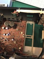
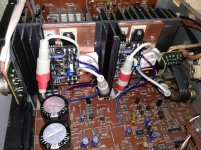
I have assembled modules but the speaker protection relay is not switching on and R408 burned out after a while also r313 r314 r315 r316 looks suspicious .
When i powered on the amplifier the dim bulb lights bright for 2 - 3 seconds and then goes barely off, amplifier stays on correctly and display lights up . Any ideas of what could be the problem?
Any help would be very appreciated.
Attachments
Last edited:
Hi Depaj, really good to hear from you. For the SU-V2, is it necessary to remove the synchro-bias circuitry? rcs16 from AudioKarma said it was not. I wanted to get your opinion directly.
Here is a picture of my completed and mounted modules.
Kind regards,
Chris
Very nice work you have done, looking very clean !
I sorted out the problems, it was an fail in GND connection(screw that connects mainboard to chassis) changed burned resistors everything works fine. BTW for bias regulation i have to turn the resistor completely clock wise for 0mV on emitter resistor ant hen slowly turn counter clock wise till 7,2 mV.
Glad for bringing back to life my old Technics. Thanks for sharing the knowledge.
Glad for bringing back to life my old Technics. Thanks for sharing the knowledge.
Hi,
Sorry guys for not answering to questions, I've been pretty submerged with things lately and didn't think to check for new posts in this thread (don't know why but I'm not getting notifications any longer even though I've subscribed). Anyway if there are issues that still need to be addressed I'm happy to help.
It's great to see this thread is still helping 😀
Hello everyone. I have been struggling with my 40 year old Technics SA-425 for several months now Technics SA-425 Plan of Attack | Audiokarma Home Audio Stereo Discussion Forums
I am a semi-retired embedded software engineer with little or no analog expertise. If you read through the thread I linked above, you will see that I've wasted a lot of time and money on bogus STK 8051/8050 replacements. I want to save this receiver and decided to build or acquire a suitable discrete replacement. I've learned from this thread that there are kits out there for this but I don't not know which one to use. I would be willing to pay someone to build a suitable replacement for both STK 8051s for my SA 425 or provide me with a kit of all the necessary parts for me to build. Any help would be greatly appreciated. Thank you.
I am a semi-retired embedded software engineer with little or no analog expertise. If you read through the thread I linked above, you will see that I've wasted a lot of time and money on bogus STK 8051/8050 replacements. I want to save this receiver and decided to build or acquire a suitable discrete replacement. I've learned from this thread that there are kits out there for this but I don't not know which one to use. I would be willing to pay someone to build a suitable replacement for both STK 8051s for my SA 425 or provide me with a kit of all the necessary parts for me to build. Any help would be greatly appreciated. Thank you.
- Home
- Amplifiers
- Solid State
- Build STK8050 equivalent