Member
Joined 2009
Paid Member
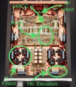
Your schematic looks as I would expect. As for the photo, you’ll have to look at the tube rectifier pin out to see if the schematic is what was implemented rather than a different arrangement. Other arrangements I’ve seen mentioned are SS diodes in parallel with the tube, effectively taking the tube out of the circuit, or a SS + tube bridge rectifier. I don’t think your photo is of the M7H, maybe a KSL or something similar. I’m building the M7H supply, more or less.
Member
Joined 2009
Paid Member
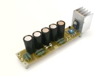
The heater supply pcb module has been assembled. My build is the image showing a single unit only (not that you couldn’t tell!). I cut up some old heatsink rather than make my own from Al plate as they appear to have done in the other image, reproduced from the manufacturer’s web site.
In my version I went with the larger TO-3P package for the power device. It’s a Sanken power Darlington, which I have several pairs of in my junk box from a Pioneer HT receiver. I don’t know what device was used in the M7H. I didn’t want to use a static sensitive device like a MOSFET, plus I like the high transconductance of a bipolar transistor. The Darlington arrangement appears to be stable in my initial testing (see earlier post) and minimizes the base current drive requirements which simplifies the design.
And again, I’ve followed the general design of the build from the M7H heater module. My version is a 6.3V supply and I may run it a bit lower than that in the final use.
Attachments

Last edited:
Hi Bigun,What I find is that these circuits simulate with rising treble responses both the original M7 tube schematic (green line in the plot above) and the version from the magazine (blue line) with an almost 3dB rise by 20kHz. This upper rise has been observed by other clone makers.
It's readily fixed in the simulation by increasing the value of the 33k resistor to 50k (use of nearest value or multiple resistors) which flattens the RIAA curve to produce a very good result.
What did Kondo intend here ? I've not built this schematic yet so I don't know how audible it is, or whether it's compensated for by other aspects of the pre-amp, or whether in fact tuning it by ear this response was deemed desirable. I'm also not sure whether it was intended to be used with a step-up-transformer (SUT) and MC cartridge or an MM cartridge, where loading can impact response. Was the RIAA voiced to suit a Kondo designed cartridge, arm and turntable?
There are too many variables to know.
Just sah this thread and your work here is amazing! After building the kit, seeing this makes me feel very lazy ..... :😀
I also noted you changed the RIAA resistor as in my build https://www.diyaudio.com/community/...hono-preamp-clone-project.358732/post-6744203 , in fact i had measured it in three different builds and the 50k really works as intended. Really begs the question why Kondo san did this in the first place......
Looking forward to see your progress! Enjoy!
Member
Joined 2009
Paid Member
Thx hesener!
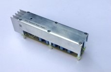
I obtained some scrap 1mm Al sheet and cut a piece for the heater supply regulator module cover. Bending with a rubber mallet and a ew holes later we have a suitable cover piece. Not perfect, holes deform, countersinks are less effective when holes don't align etc. Anyhow, saves me from explaining which image is my work and which is from the manufacturer's website !
A safe cover is advisable because the heater supply will be at an elevated voltage, to reduce heater-cathode insulation stress.
I used some heat sink compound between the cover and the thick plate of the heatsink, hopefully enabling the cover to act as an extended fin for the heatsink.
Attachments

Member
Joined 2009
Paid Member
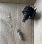
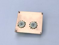
I have a set of front panel knobs, recovered from some old donor item. They just happen to match up with what I need for the old M7 look and style. They are all for 6mm knurled shafts / actuators.
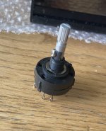
A challenge is the on / off switch. I couldn’t locate a ready-to-go 2-way rotary switch with a knurled shaft so I had to make use of one with a 1/4” flattened plastic shaft. From the previous installation of aluminium extension rods on other controls I has some left over rod with knurled ends. So I cut the plastic shaft down and cut a larger flat. Then I cut the aluminium rod down, cut a flat with a hacksaw too. I drilled the rod, with a 2.4mm drill and then used the rod to self-align and drill the plastic shaft. I widened the hole on the plastic shaft to 3mm and tapped the rod to M3. This allowed me to graft the knurled rod onto the plastic shaft, a dab of epoxy and an M3 screw. But….Jeez, would have been easier if I could have located a proper switch.
A challenge is the on / off switch. I couldn’t locate a ready-to-go 2-way rotary switch with a knurled shaft so I had to make use of one with a 1/4” flattened plastic shaft. From the previous installation of aluminium extension rods on other controls I has some left over rod with knurled ends. So I cut the plastic shaft down and cut a larger flat. Then I cut the aluminium rod down, cut a flat with a hacksaw too. I drilled the rod, with a 2.4mm drill and then used the rod to self-align and drill the plastic shaft. I widened the hole on the plastic shaft to 3mm and tapped the rod to M3. This allowed me to graft the knurled rod onto the plastic shaft, a dab of epoxy and an M3 screw. But….Jeez, would have been easier if I could have located a proper switch.
Attachments
Member
Joined 2009
Paid Member


Member
Joined 2009
Paid Member
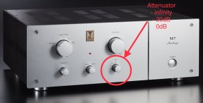
The M7H also sports a front panel selector for an attenuator. I’m assuming this is not like the original M7 that had gain adjustments for the inputs, but rather this is an attenuator ahead of the line amp. Modern systems don’t always need the dull gain of an active line amp but do want the high input impedance and low output impedance of a line amp (so you don’t want your attenuator after the line amp or you increase the output impedance and load down your line amp).
I’m including this attenuator in my clone. Looking at the front panel f the M7H they appear to have designed it to act as a mute (- infinity dB), or low gain line amp (-20dB), or full gain line amp (0dB att.).
I’m including this attenuator in my clone. Looking at the front panel f the M7H they appear to have designed it to act as a mute (- infinity dB), or low gain line amp (-20dB), or full gain line amp (0dB att.).
Attachments
Member
Joined 2009
Paid Member
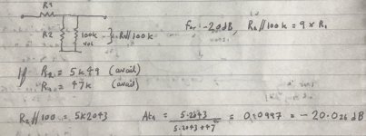
I’ve considered a few options and the only one that makes sense is a ladder attenuator (which I’ve also employed for the volume control).
And there’s a bit of math involved to choose the values to achieve -20dB When the attenuator is playing into the 100k impedance of the volume control.
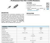
All the signal level resistors I’m using in this build are going to be Vishay Beyschlag, metal film MRS25, to ensure adequate quality with adequate voltage ratings for the tube circuits.
And there’s a bit of math involved to choose the values to achieve -20dB When the attenuator is playing into the 100k impedance of the volume control.
All the signal level resistors I’m using in this build are going to be Vishay Beyschlag, metal film MRS25, to ensure adequate quality with adequate voltage ratings for the tube circuits.
Attachments

Last edited:
Member
Joined 2009
Paid Member
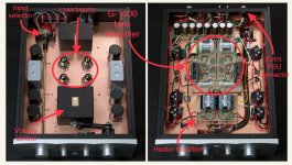
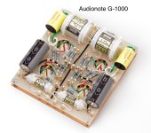
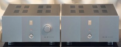
I want to move on to look at the signal circuitry. The top end of the range are separates and rather than continue to copy elements from the M7H design I am going to take my inspiration from these separates, starting with the Line Amplifier.
And it looks to adopt the key elements of the power supply from the M7H, the types of capacitors and construction all more or less the same. The G-1000 is a stereo unit but I will build just one mono channel.
The G-1000 Line Amp
And it looks to adopt the key elements of the power supply from the M7H, the types of capacitors and construction all more or less the same. The G-1000 is a stereo unit but I will build just one mono channel.
Attachments

Last edited:
Member
Joined 2009
Paid Member
Looking at the published images of the Line Amp I can extract the design, the layout, components etc. I’ve taken a stab at determine the component values and with some assumptions based on earlier models I’ve made an educated guess at the operating points (voltages and currents) too. I’ve included knowledge about low noise operating points from the GE datasheet for the 12AY7/6072 (a reference gleaned from the Vinyl Savor website tube of the month Feb 2020) which suggests lowest noise is achieved at approximately 1.1mA per plate.
First off, the design is very much similar to the M7/M77/M7H. Why change what is already popular?
The triodes are doubled up in this version. I’ve read different viewpoints about this, many negative comments included. However, very little in the way of data although see attached comments from elsewhere on this forum.
The standing current through the tubes looks to be set up at a bit higher than the earlier models, something that others have experimented with and have said they preferred the sound with a higher current. This change seems to be part of the commercial version of this Line Amp now.
Attachments
Last edited:
Member
Joined 2009
Paid Member
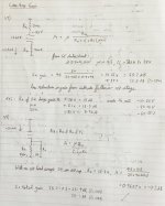
The amplification stage is the dual 12AY7, common cathode. The plate curves can be used to determine the approx operating point (Attached).
The combined triodes will have half the effective internal resistance and double the effective transconductance, so the gain mu will be the same.
The gain with an un-bypassed cathode resistor calculates around 25.5dB
The cathode follower output stage will be loaded by Rk // the 1M resistor placed after the output capacitor (to prevent it from charging with static when left open Etc.). The gain is around -0.3dB.
So the overall Line Amp gain is designed at around 25.2dB (consistent with published specs.)
Attachments

Member
Joined 2009
Paid Member
I’m not buying Kondo’s silver capacitors or tantalum resistors but I’m going to copy this module with some good quality parts all the same.
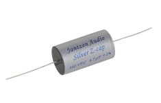
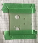
For the output cap I’ve chosen to go with a Jantzen Silver z-cap. I’ve not used them before, but they have a good reputation and besides, they also ‘look the part’. To minimize phase shifts at low frequencies when driving into low impedance amplifiers I’m using a relatively large 4.7uF cap. This large cap will have to be tied down on the board as is done in the G-1000. To this end I’ve fashioned a piece of FR4 board and cut a matching piece of copper sheet from the same stock that I made the chassis-shelf with. The FR4 board was then fashioned with slots for tie wraps to pass through and holes for the valve wiring.
I’ve duplicated the G-1000 board layout, with extra space for the z-cap and I’ve used green masking tape to fix the board to the back of my layout drawing. Next step is to centre punch through the paper where each turret will be located and then drill all the holes (2.4mm dia).
Attachments

Last edited:
Member
Joined 2009
Paid Member

Member
Joined 2009
Paid Member
Member
Joined 2009
Paid Member
OK, I now have a single channel G-1000 Line Amp module. The manufacturers image is of their stereo version of course but I’ve managed to keep my version faithful to their original to the best that I’m willing to pay for! Haven’t double-checked the wiring yet. It needs to be installed in the chassis and wired up too. And I’m still waiting on a Eurotubes shipment before I can install the valves and do an initial power up this module.
Attachments

Member
Joined 2009
Paid Member
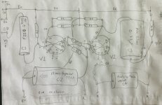
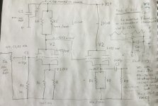
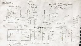
Until I get more done on the Line Amp I might as well move on to the last piece, the phono amp. I don’t want to copy the M7H design, it deviates from the original in topology, using an SRPP circuit instead of a cascode. So I’m going to copy their flagship phono amp instead, which retains the original topology. This is the..
With a gain of 38dB it’s designed for direct connection to MM cartridges. It uses the E88CC at the front end and 12AY7’s for the final stages. The design, construction and parts choices are in the same character as for the M7H and G-1000.
Kondo GE-10 Phono Amplifier
With a gain of 38dB it’s designed for direct connection to MM cartridges. It uses the E88CC at the front end and 12AY7’s for the final stages. The design, construction and parts choices are in the same character as for the M7H and G-1000.
Attachments
Member
Joined 2009
Paid Member
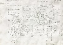
I have used published information to sketch out the circuit of the GE-10 phono stage, a cascode input driving a passive RIAA network, followed by a gain stage and output driver. The cascode upper tube is fully biassed by a filtered dc supply. Not all parts values are easily obtained, some thought was needed which will need to be tested out after it is built.
Attachments
Last edited:
Member
Joined 2009
Paid Member
And construction of the phono amp is along the same lines as the Line Amp. However, there are some physical limitations to where I can locate the valves to keep them away from things on the chassis so the layout is similar but a bit distorted from the original GE-10 module. The valves have arrived so I’ve got everything I need to build this thing!
Attachments


Member
Joined 2009
Paid Member
Yes. Which means you may have spotted the issue I'm working on next - the power transformer is putting out too high a voltage and I need to tame that further before I can get the H.T. down to 260V. There's no "per side" as this is a mono implementation. The Line Amp will draw the least and the phono amp the most, some current draw from other sources includes the resistor divider for heater elevation and some t.b.d. bleeder resistors on main caps for safety.
- Home
- Amplifiers
- Tubes / Valves
- Build of Kondo M7 -> Kondo-Ashizawa M7H -> G-1000 & GE-10 upgrade