Hi All,
As @Bigun rightly mentioned I take my own path by INCLUDING M7 clone in my own design of integrated amp (pre and power amp in one box)
Here I have another question. It would be much appreciated if you can help, please.
I own already, perfectly running SE EL84 tube amp. This is well known and proven design of Mr Alex Kitic called RH84. Some love it some don't, some are questioning use of silicone current sink - let's leave this discussion absolutely aside. Since I have speakers of 96dB efficiency I search no further in here. HOWEVER standard source can't fully drive the amp.
This is the reason I am trying to add nice preamp. So far I am running old Audio Note UK project called L2. But I want to try something new 🙂
Therefore I am trying to replace AN UK L2 clone with Kondo M7 🙂
Here comes the question - volume potentiometer (blue frame at drawings) and connection:
I see two options
1/. Potentiometer at the beginning of the chain and then directely preamp to amp (see illustration below). BUT I don't know should I keep both 1 mog resistors (marked Rx and Ry in red frame)? They will go in pararell (500kohm) that literally makes no sense (?) for me. So I think I should remove one of them. Is it correct way of thinking?
DRAWBACK - I am afraid of "natural" kind of pink/white/granular noise of every circuit (especially tubes) - preamp output permanently feed power amp input with full amplified voltage (INCLUDING NOISE)

2/. Another option is to place potentiometer BETWEEN preamp and power amp (again in the bluw frame)
And again the same critical question - resistors Rx and Ry (red frames) - should they stay as they are or shoud I modify/remove ?
BENEFIT - on lower volumes natural circuit noise will be limited by potentiometer (and on bigger volumes doesn't matter anyways 🙂).

As @Bigun rightly mentioned I take my own path by INCLUDING M7 clone in my own design of integrated amp (pre and power amp in one box)
Here I have another question. It would be much appreciated if you can help, please.
I own already, perfectly running SE EL84 tube amp. This is well known and proven design of Mr Alex Kitic called RH84. Some love it some don't, some are questioning use of silicone current sink - let's leave this discussion absolutely aside. Since I have speakers of 96dB efficiency I search no further in here. HOWEVER standard source can't fully drive the amp.
This is the reason I am trying to add nice preamp. So far I am running old Audio Note UK project called L2. But I want to try something new 🙂
Therefore I am trying to replace AN UK L2 clone with Kondo M7 🙂
Here comes the question - volume potentiometer (blue frame at drawings) and connection:
I see two options
1/. Potentiometer at the beginning of the chain and then directely preamp to amp (see illustration below). BUT I don't know should I keep both 1 mog resistors (marked Rx and Ry in red frame)? They will go in pararell (500kohm) that literally makes no sense (?) for me. So I think I should remove one of them. Is it correct way of thinking?
DRAWBACK - I am afraid of "natural" kind of pink/white/granular noise of every circuit (especially tubes) - preamp output permanently feed power amp input with full amplified voltage (INCLUDING NOISE)
2/. Another option is to place potentiometer BETWEEN preamp and power amp (again in the bluw frame)
And again the same critical question - resistors Rx and Ry (red frames) - should they stay as they are or shoud I modify/remove ?
BENEFIT - on lower volumes natural circuit noise will be limited by potentiometer (and on bigger volumes doesn't matter anyways 🙂).
Last edited:
Member
Joined 2009
Paid Member
You keep Rx because it protects the output capacitor from static charges etc. when the interconnect with the amplifier is not present. It's simply good practice. You keep Ry in case the potentiometer wiper goes open circuit. Personally I don't think there's any issue with Rx, potentiometer, Ry. You are fine with what is shown in your 2nd schematic.
@Bigun THANKS!!! Last one - assuming I will make connection as figure 1 (potentiometer at the circuit beginning) and no "circut noise" - hope you know what am I reffering to (a kind of pink/white noise coming from tubes, resistors, introduced partialy by PS, etc, etc) - will NOT be audiable or negliable audiable in the tweeter; then, under this condition, my gut feeling tells me it's better to make configuration from figure 1. Am I right?
From this point - still assuming I will select this path - what about Rx and Ry? They clearly and directly goes in pararell, that makes 500kom out of this...
PS - situation that output will be open, will never happen, as this is obe box, hardwired construction. Same potentiometer goes open will never happen as it is stepped attenuator with "phisical", solid resistors on relays. So this is no concern.
Question - IF I select concept from graph 1 - should I skip one of resistors (like below)?
Member
Joined 2009
Paid Member
I'd recommend against leaving our Ry, it's "bad practice" but you are free to do so of course.
Noise - is a big topic. These resistors are in parallel to the signal, they are not what you need to worry about.
Tube noise - using good quality tubes and if necessary, selecting by ear the lowest noise tubes.
Noise - is a big topic. These resistors are in parallel to the signal, they are not what you need to worry about.
Tube noise - using good quality tubes and if necessary, selecting by ear the lowest noise tubes.
@Bigun - I totally understand what you saying. My concern is: imagine that circuit is, physically designed on ONE pcb board. So we have traces continuity guaranteed. Don't think about M7 as separate device to power amp, in my construction. It is one individable box, soldered circuit. Having this in mind: looking at current schematic I have two (Rx and Ry) resistors, permanently connected. My concern is they are connected in parallel. So 1mohm/2 = 500kohm. For that reason I was thinking it's better to remove one to keep 1mohm resistance value. And good practice is still kept (if I understood your point correctly) as you can NOT separate preamp from power amp (again, one, permanently soldered device).
Or other way round - what does it change for the circuit if there is 500kohm (2 x 1meg in pararel) or 1mohm? What are your thoughts on that please?
Or other way round - what does it change for the circuit if there is 500kohm (2 x 1meg in pararel) or 1mohm? What are your thoughts on that please?
Member
Joined 2009
Paid Member

@Bigun thanks you for extensive support! Highly appreciated. Last thing - if you were me (assuming noise and hum will not be an issue) ‐ would you go for solution 1 with potentiometer at the beginning and direct connection between preamp and amp or you would make configuration 2 with potentiometer in the middle? I personally feel that solution with potentiometer at the input (1) is technically and potentially sonically, as well, more "elegant". What would be your advice? Did you ever performed any test on this topic?
Member
Joined 2009
Paid Member
I personally prefer the potentiometer before the Line Amp. Obviously, in the case of a Phono Amp the potentiometer goes afterwards, again before the Line Amp. In this way, there is no potentiometer after the Line Amp which would compromise the output impedance driving into the power amp.
The M7 Line Amp has a lot of gain, unsuitable for many modern power amps. You may want to think about a -20dB attenuator, as I did when I build mine.
The M7 Line Amp has a lot of gain, unsuitable for many modern power amps. You may want to think about a -20dB attenuator, as I did when I build mine.
@Bigun for my curiousity - could you please share how have you implemented attenuator? Just hand drawing on piece of paper and mobile phone photo shared here would make perfect job, if I may ask. Thank you 1I personally prefer the potentiometer before the Line Amp. Obviously, in the case of a Phono Amp the potentiometer goes afterwards, again before the Line Amp. In this way, there is no potentiometer after the Line Amp which would compromise the output impedance driving into the power amp.
The M7 Line Amp has a lot of gain, unsuitable for many modern power amps. You may want to think about a -20dB attenuator, as I did when I build mine.
Member
Joined 2009
Paid Member
Member
Joined 2009
Paid Member
All JJ
(don't buy a darn thing from Russia, which is where Electro Harmonix gets their tubes from)
(don't buy a darn thing from Russia, which is where Electro Harmonix gets their tubes from)
Last edited:
Fair point about ban for soviet union products (sometimes called russian to create misleading impression 😁). Did you pick gold version of JJ or regular (red label). PS - happy with this JJ's?
Member
Joined 2009
Paid Member
I haven't enough experience to comment on different tube manufacturers - in the case of this project I just plumped for the JJs and found that I liked the results. I didn't go with the gold pin version. Something in me wrankles at the idea that gold plated pins are somehow better but if somebody can say otherwise I'll might try them in the future.
Member
Joined 2009
Paid Member
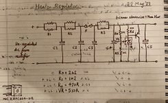
'patrik96' recently asked about the values of the resistors I used in the heater regulator,
"... didn't see the resistors for the TL431 ref input there"
I've uploaded a photo from my notebook where I noted down the resistor values.
The power PNP transistor notes are not there - I'm pretty sure that I used a Sanken Darlington for the job, as I have a bunch of them from an old Pioneer multi-channel receiver I was messing with once ( I still have a bunch of NPN and PNP power Darlington devices made by Sanken that I hold in high regard). This helps you figure out that there are 2xVbe drops in my choice of power transistor, hence with the value of the resistor R6 at 470R the current through the 431 device must be roughly 1.2V/470R = approximately 2.5mA and this is a nice operating point for it.
Attachments
Last edited:
- Home
- Amplifiers
- Tubes / Valves
- Build of Kondo M7 -> Kondo-Ashizawa M7H -> G-1000 & GE-10 upgrade