Member
Joined 2009
Paid Member
Member
Joined 2009
Paid Member
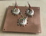
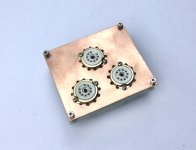
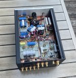
Now the final module is built. The Kondo stereo module sports a raft of silver caps. In my version, a mono module, I’ve used polystyrene caps in the RIAA and a Jantzen Silver Z-cap at the output.
My module remains untested. I should review the wiring carefully before I think of applying power to it. I expect it’ll take awhile.
My module remains untested. I should review the wiring carefully before I think of applying power to it. I expect it’ll take awhile.
Attachments


Member
Joined 2009
Paid Member
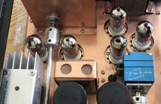
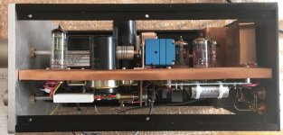
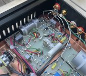
I’ve wired up the heaters and installed my recently arrived tubes from JJ.
The HT is not yet wired up. I want to leave on just the heaters, allowing everything to heat up for about an hour. The tube heaters are glowing and the voltage is set around 6V; I noticed that the heatsink on the heater supply shunt regulator is nice and warm. The heater supply filter caps were noticeably warm and I suspect this will limit their service lifetime.
Otherwise, all seems to be well so far.
Attachments
Last edited:
Member
Joined 2009
Paid Member
I got distracted but now making progress again. The HT supply has been wired up to the boards and then powered up. Two problems,
a) the heater supply filter caps are hot, not too hot to touch or anything but hot enough that I worry about longevity; I’ll look at improving the ventilation.
b) the HT supply to the phono amp is unstable. And I’m pretty sure it’s parasitic oscillations.
I’ve rewired all the tube sockets to add 1k grid stoppers to all grids, both boards, right at the pins (10 total). I’ve added 100R cathode stoppers to all the cathodes being used as Followers, both boards, again right at the pins (4 total). And I added a 100R anode stopper to the upper cascode of the phono amp.
I’ve added a couple of film caps on-board of the phono amp across the HT - Gnd, one near the output stage and one near the input tube. I added an on-board film bypass across the heater wires for good measure. Added another on the Line Amp board.
Stability is now much improved. It’s not perfect, there can be some touchy behaviour when probing around the cascode with a DMM probe and I’ve seen a sporadic outbreak of instability during warming up. The E88CC is one squirely tube. I think I’ll power up a ‘scope as the next step.
Attachments

Last edited:
Member
Joined 2009
Paid Member
It’s been at least a year since my scope was powered up. Just for kicks I connected it up to the pre amp to have a play. No serious measurements.
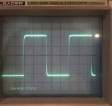
The HT power supply voltage to the front end of the phono was very clean, thankfully. The phono amp produced a very distorted square wave, as would be expected with a non-flat RIAA filter. On sine waves it produced, well, sine waves. All the way up to at least 100kHz. The bottoms of the sine waves were starting to distort when the output was above 10Vpp, getting noticeable above 15Vpp. There was some h.f. hash, sporadic but I couldn’t trigger the scope on it and it was happening only once in a few minutes so not much chance to investigate.
The Line Amp produced nice looking square waves. Attached image at 10kHz.
Looking at the amplitude, it was possible to confirm proper operation of the selector switch, attenuator switch and the volume control.
Attachments
For this duty i'm using 10,000hr @ 105C caps. If the caps are warm - what about dropping voltage resistors in series ?the heater supply filter caps are hot, not too hot to touch or anything but hot enough that I worry about longevity;
I am asking because for this same duty i had to drop around 2 Vdc and did it in C-RC before regulator with resistors being 20W types and they are hot ( 0,9A totall from heating 6N1P + E180F ). Actually they are much hotter than capacitors ( first is warm, second not so much and both not enough to worry ).
Member
Joined 2009
Paid Member
Yes, that’s what I have already, rectifier -> dropping resistors -> caps. The resistors run hot. But I’m running at around 1.7 Amps (5 valves plus something for the regulator). I checked my Digikey order and I’m using Rubycon 16V 10mF 105degC caps - that gives some peace of mind. The ventilation is terrible though, something my drill stand needs to fix today!
Member
Joined 2009
Paid Member
Member
Joined 2009
Paid Member
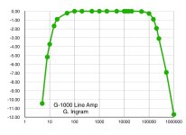
I measured the freq response of the Line Amp. Not perfectly accurate, just using a signal generator (+/- 1V O/P) and scope, no load. It looks pretty close to the manufacturers published spec (-3dB at 8Hz and 280kHz). The low end cut off is determined by the input cap (0.022uF) and grid leak (1M).
The line amp has a prodigious output swing if it wants, so it could serve as a direct input to a unity gain power amp such as the Pass F4.
The line amp has a prodigious output swing if it wants, so it could serve as a direct input to a unity gain power amp such as the Pass F4.
Attachments
Member
Joined 2009
Paid Member
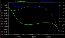
I didn’t find it so easy to measure the RIAA curves with my sig gen and scope because the range of values is so wide. But I had a go at it and found it to be reasonable. My data in green, RIAA in blue. The manufacturer specifications are +/- 0.5dB over the range 30Hz to 20kHz. Note, they incorporate a resistive load after the output cap to pull down the sub-sonic level at the output and I’ve done exactly the same thing in my build.
Thankfully, I’ve not had much trouble with parasitic oscillations or other obvious signs of instability after finding a couple of dry joints, heck one of them hadn’t been soldered at all! Perhaps the tubes have had some time to settle down too. FWIW, I was able to observe an occasional multi-mV signal on the output at roughly 25MHz (looked like a sine wave, not a modulated signal) but it was present even with the unit powered down and unplugged and appears to be riding on the earth connections so it’s external to my preamp and is something else In the environment.
It seems to me that the next steps should involve listening to it.
Attachments

Last edited:
Member
Joined 2009
Paid Member
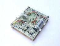
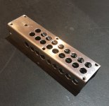
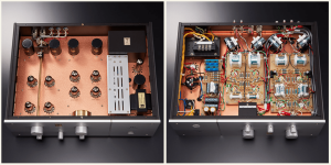
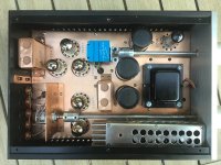
Some underside photos of what may turn out to be a finished state, we’ll see. Working on it has been made easy by fitting the bottom cover, complete with rubber feet, to the top of the chassis enclosure and sitting the unit on the bench upside down.
Also attached an image of the commercial M7H that has served as part of the inspiration.
Also attached an image of the commercial M7H that has served as part of the inspiration.
Attachments
Member
Joined 2009
Paid Member
It sings!
I was able to connect it into a temporary set-up. TT -> M7 -> TGM8 (SS power amp) -> Big'un full range 15" speaker
"First Sound" Initial observations:
Once all powered up there was no hum. There was some low level 'tube hiss' which was heard when placing myself near the speaker. I could change the level of hiss slightly with the attenuator and input selector but interestingly it was not dominated by the phono stage because it dropped only a bit when I set the input selector switch to an unused input. This means that the phono is behaving well from a noise perspective despite it's high gain. Of course the gain structure is non-optimal because my TGM8 power amplifier has quite a bit of gain and doesn't need gain from a pre-amp. The gain structure being what it is means using the -20dB atn. setting on the front panel, a resistive ladder switched in or out and which sits before the volume control before the Line Amp. The output from the phono amp is plenty enough. The whole chain as I have it today for testing has simply too much gain at each stage. The end game for my set up is to use a valve amplifier.
M7: phono -> input selector switch -> attenuator (0db, -20dB, mute) -> volume control -> Line Amp
There was a turn-off 'crack/pop' and so I've now added an RC snubber across the primary of the power transformer to see if this helps. The main power switch is double pole. Will test this out next time.
I haven't used this large speaker for awhile, having had a pair of B&W CM4's in place so my initial impression was dominated by the differences between the speakers. Once I had re-accustomed myself to the full range speaker everything fell into place. The sound was simply good. No harshness, no sense of frequency response anomalies (none expected - I will tell more about the RIAA later), it did not sound 'tube coloured' to my ears either.
Last edited:
Member
Joined 2009
Paid Member
RIAA Accuracy
=========
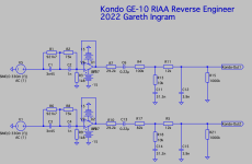
Much has been written about the non-flat RIAA response of the original M7 and I was curious to see whether the latest from Kondo's company had corrected this or if it was a House Sound to be preserved.
When I ran a Spice simulation I found that it was pretty flat, assuming that the source impedance was vanishingly low. In other words, a kind of text book design.
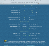
But the tube phono has a finite drive impedance for the RIAA network. The output impedance from the E88CC cascode is not going to be that low. I used an online calculator to save me the trouble of calculating it myself (ref: Keith-Snook) which provided an Rout of 29,158 Ohms. That's not vanishingly low. Re-running the Spice simulation shows this upsets the RIAA conformance.
Did the new design team at Kondo make a mistake ? Were they aiming for flat and didn't account for this impedance ?
In the end I decided to adjust the value of the first resistor in the RIAA filter, reducing it from 100k to 82k to compensate for the driving impedance. From simulations this should provide much better RIAA accuracy. My measurements were limited in accuracy but the results look fine and they sound fine.
=========
Much has been written about the non-flat RIAA response of the original M7 and I was curious to see whether the latest from Kondo's company had corrected this or if it was a House Sound to be preserved.
When I ran a Spice simulation I found that it was pretty flat, assuming that the source impedance was vanishingly low. In other words, a kind of text book design.
But the tube phono has a finite drive impedance for the RIAA network. The output impedance from the E88CC cascode is not going to be that low. I used an online calculator to save me the trouble of calculating it myself (ref: Keith-Snook) which provided an Rout of 29,158 Ohms. That's not vanishingly low. Re-running the Spice simulation shows this upsets the RIAA conformance.
Did the new design team at Kondo make a mistake ? Were they aiming for flat and didn't account for this impedance ?
In the end I decided to adjust the value of the first resistor in the RIAA filter, reducing it from 100k to 82k to compensate for the driving impedance. From simulations this should provide much better RIAA accuracy. My measurements were limited in accuracy but the results look fine and they sound fine.
Attachments
Member
Joined 2009
Paid Member
Dark Side of The Moon, a modern pressing. I am listening to it now, just great. This is probably the best play back chain I’ve ever owned for vinyl. And quite a level above anything previous. That’s a bit shocking when I think about it, given how long I’ve been in the hobby. The credit goes to the TT mostly. Nevertheless, it seems that the M7 stays out of the way just as it should, and the overall chain just brings forth Pink Floyd full of life. The sound is just alive.
I can’t yet envision any motivation to explore tweaks and changes to my M7. It maybe that the speaker is now the new bottleneck here.
Still haven‘t figured out why there’s some audible hum before the tubes are ready, a hum which just suddenly blinks out of existence some good seconds after the M7 is powered up, presumably when the tubes are then conducting.
Now on to Billy Paul, Me and Mrs Jones. What a voice. Rendered with so much life.
Last edited:
RIAA Accuracy - as i recall from the beginning there was not one correct schematic for these preamps - like you did, there should be a good look what is really inside and then calculate the proper values for the clones to work as they really could.
Member
Joined 2009
Paid Member

Wow, what an incredible build, well done! 😀
Very impressed from England!
What does it sound like?
Rich
Very impressed from England!
What does it sound like?
Rich
Member
Joined 2009
Paid Member
Hi Rich, thanks for the words,
Sounds bloody marvelous!
I can only say that the system overall sounds just great, hard to isolate any component But this is the best sound I’ve ever had with my existing speaker and amp.
There are a lot of different parts in this unit, it could have taken years to sort out which combination of capacitor types were needed for the best sound, which power supply topology, choice of valves, bias points, hardware etc. Life being short my approach was to copy these things from the stable of Kondo where talent and experience was not in question. It does mean relying on some body else’s taste but much has been written about these designs to give me confidence.
My background is science and technology, so I like to know how the design works, what likely drove the design choices made so rather than just blindly copy I also go through a process of reverse engineering it all and questioning. Not only makes the journey more interesting but builds confidence in the design.
By following the Kondo design and duplicating to some level the construction method, use of specific materials and then chasing down specific brands for the parts, I gave myself a good chance of achieving a good result first time out. And after another evening of playing records I am very impressed! It beings a natural life to the music I’ve not experienced before and now there’s no going back. This is going to be the end point for a pre-amp for my mono system.
Last edited:
- Home
- Amplifiers
- Tubes / Valves
- Build of Kondo M7 -> Kondo-Ashizawa M7H -> G-1000 & GE-10 upgrade