Member
Joined 2009
Paid Member
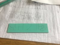
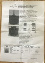
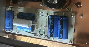
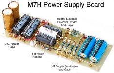
Back to that heater supply. Found another picy of it with the cover removed. Actually, there are a few images but none of them are of the exact same supply unit. There are some subtle differences, changes or just product variations I don’t know.
Anyhow, it looks simple enough to make one for my project. I’ve got some copper clad board to cut to size and I‘m going to try and make this one myself.
Anyhow, it looks simple enough to make one for my project. I’ve got some copper clad board to cut to size and I‘m going to try and make this one myself.
Attachments

Member
Joined 2009
Paid Member
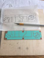
I’m going to try a technique that I’ve not used before. A sheet of sticky-back vinyl from the art & craft store. The idea is to cover the copper side of the board and them mark out the traces before cutting the vinyl into the right shape. It will perform the duty of an etch resist.
Attachments

Member
Joined 2009
Paid Member
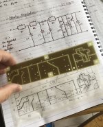
Just like the days before computers… I drew a rough component layout and then, placing air mail (used as tracing) paper over it I devised the cut lines pattern for the copper. Then reversing the paper onto the vinyl clad board I used a pencil to go over the pattern which transferee the pencil lead onto the surface.
There‘s no DRC software, or ERC for that matter so then chances of human error are quite present.
There‘s no DRC software, or ERC for that matter so then chances of human error are quite present.
Attachments

Member
Joined 2009
Paid Member
Member
Joined 2009
Paid Member

That’s a very slick approach to making a circuit board. I haven’t etched my own boards for over 20 years and these days I use point-to-point wiring, but if I ever do make some more boards I will try your technique.
Member
Joined 2009
Paid Member
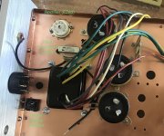
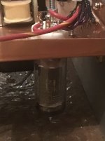
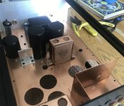
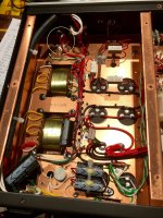
I’ve started to get the power supply parts mounted on the chassis. In the end I decided to add a filter choke to be consistent with the M7H design. I had very little space but a friend had a new small Hammond choke in his parts bin. It’s not going to get abused much, this being a capacitor input power supply the choke will only ‘see‘ the residual ripple after a post rectifier RCRC input filter. It’s rated to 300V (although HiPot tested over 1kV) whereas the HT will be a bit above at this point in the supply, which means the best approach will be to place it in the ‘ground’ leg of the supply where it will see relatively low voltages (why don’t we always do it this way?).
And I’ve added a bridge rectifier for the heater power supply, rated 6A continuous it should do fine bolted down against the copper chassis there.
And I’ve added a bridge rectifier for the heater power supply, rated 6A continuous it should do fine bolted down against the copper chassis there.
Attachments
Member
Joined 2009
Paid Member
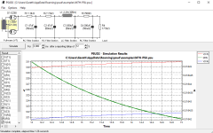
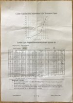
Running a Psud simulation of the M7H power supply, but based on my Hammond 273AZ transformer specifications and a total current draw on the HT supply for my build of around 18mA to 19mA. This suggests a value for the input resistor, which limits current through the rectifier as well as pulling down the voltage.
Just like a choke input supply, without a current draw the HT voltage will rise above the design target. The first two caps I've installed are rated at 500V and can handle this but I've used smaller caps further downstream closer to the active circuitry and a lack of current draw would lead to an over-voltage of the power supply capacitors further downstream where ratings are lower.
With an indirectly heated rectifier tube the HT shouldn't come up too fast but I see now that my approach is not fail-safe.
Attachments
Last edited:
Member
Joined 2009
Paid Member
Member
Joined 2009
Paid Member
Some more progress with the M7H power supply.
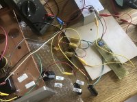
The front-end of the HT supply is now done. An EZ80 into a 47uF cap via a 1k2 resistor to both drop volts and smooth out those current charging pulses. The large resistor spreads the heat out so it‘s running just warm but not hot, with the supply loaded down to deliver around 18mA. Then a 1k8 power resistor to another 47uF cap (same can, dual cap) and this resistor is just slightly warm.
The heater supply has now been completely bread-boarded. Found a silly error on my PCB that required me to cross two legs on the TL431 but it’s running. I can adjust the voltage using the trimmer pot. I have a 3.3R load on it to draw more than it’ll have to do in real use so it’ll all run slightly cooler. Some work to put it into a final form and as I’m off on travel again this will have to wait until July.
Good thing is that the supplies are all working as intended so it can be built out with confidence.
Attachments

Member
Joined 2009
Paid Member
I’m back from several weeks of travel and finish up of quarter end at the day job.
So, back to the project and this morning I cut up some Aluminium to make a mounting bracket for the volume control. It’s a stepped attenuator, ladder topology, nominal 100k.
So, back to the project and this morning I cut up some Aluminium to make a mounting bracket for the volume control. It’s a stepped attenuator, ladder topology, nominal 100k.
Attachments

Member
Joined 2009
Paid Member
Member
Joined 2009
Paid Member
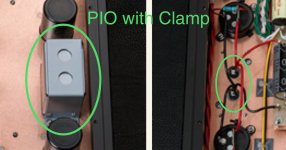
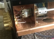
I noticed that the M7H uses PIO caps. You can see the grey coloured item in the attached photo. I’m confident this grey item is a PIO from looking at the photo of it, both above and below the M7H chassis.
I’ve just loosely installed two brown coloured high quality PIO caps I sourced from the Ukraine, into the chassis using copper straps fashioned from left over copper sheet. The copper straps are a bit ‘rough‘ and short but they’ll do. You can see one of them in the attached photo of my chassis - which is showing a bit more progress now.
I’ve just loosely installed two brown coloured high quality PIO caps I sourced from the Ukraine, into the chassis using copper straps fashioned from left over copper sheet. The copper straps are a bit ‘rough‘ and short but they’ll do. You can see one of them in the attached photo of my chassis - which is showing a bit more progress now.
Attachments
Member
Joined 2009
Paid Member
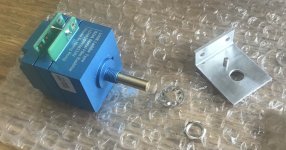
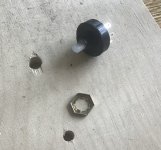
On the left, a plastic rotary switch, brand new from Digikey, sporting some kind of stamped combination nut-washer. The nut slips under force, the actuator is sloppy and the action poor. Yup, it's Utter utter, utter, complete CRAP!
And on the right, the final solution, a new metal rotary switch from AliExpress. Solid, really nice action. Less expensive too.
Digikey are going the way of HomeDepot, customers want cheap so let’s give it to ‘em!
And on the right, the final solution, a new metal rotary switch from AliExpress. Solid, really nice action. Less expensive too.
Digikey are going the way of HomeDepot, customers want cheap so let’s give it to ‘em!
Attachments

Member
Joined 2009
Paid Member
Member
Joined 2009
Paid Member
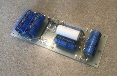
I’ve now finished recreating the M7H power supply board (refer back to post #45) and installed it to the chassis underside. I’ve followed closely (not exactly) the same design, parts choices and build method. My version is slightly simplified and of course is a mono version.
Attachments
Hi Bigun. Refering to your PSU schematic on post #46 for the tube rectifier, I saw from the original picture two diodes on the rectifier tube pins (see on the picture, circled in Yellow), they are not on your schematic. I think they are refered in the litterature as 'Backup diodes'. Any thought on that?
SB
SB
Attachments

Member
Joined 2009
Paid Member
Are you showing an M7H in that image, I’m not sure those diodes showed up in the manufacturer’s images I have. They may not be part of the official design.
Nevertheless, they are a good idea and I had intended to include series diodes but I forgot about them when I was prototyping the psu as my focus at the time was to see if the actual voltages under load matched expectations. I even have a pair of suitable diodes ready to use. As you likely know already, the purpose of these diodes is to protect everything from possible damage in the case of a failed or faulty tube rectifier. They might also reduce reverse voltage stress on the rectifier.
Nevertheless, they are a good idea and I had intended to include series diodes but I forgot about them when I was prototyping the psu as my focus at the time was to see if the actual voltages under load matched expectations. I even have a pair of suitable diodes ready to use. As you likely know already, the purpose of these diodes is to protect everything from possible damage in the case of a failed or faulty tube rectifier. They might also reduce reverse voltage stress on the rectifier.
Last edited:
- Home
- Amplifiers
- Tubes / Valves
- Build of Kondo M7 -> Kondo-Ashizawa M7H -> G-1000 & GE-10 upgrade