Member
Joined 2009
Paid Member
Looking around at various images it seems that there’s quite a mix of parts. Power supply relies on plenty of aluminium electrolytic capacitors (RC filters) rather than any type of regulation or even a choke. Chokes can be heavy and if not carefully positioned can spew magnetic interference into other circuits and wiring (I have a power amp that suffers a bit from this).
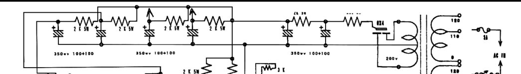
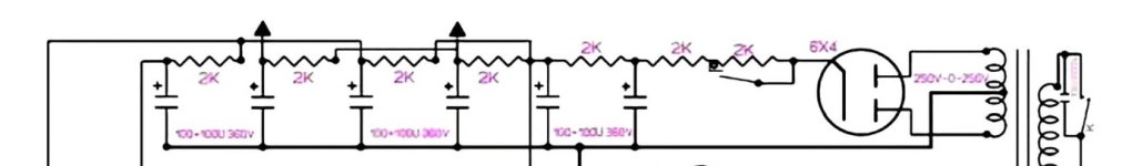
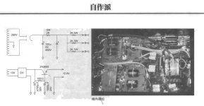
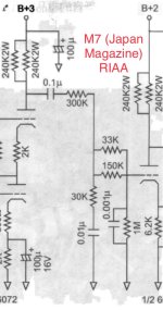
The psu schematics floating around for the M7 and M77 are very similar. Hollow state rectifier with capacitor input filter (via peak current limiting resistor to protect the rectifier etc.). Then parallel RC filters to provide reduced ripple and some isolation between stages and circuits for the H.T. The third image is from a Japanese magazine, doesn’t show a resistor before the first cap, but perhaps this was unnecessary due to sufficient winding resistance in the power transformer secondary.
I’m hoping that the slow warm up of this approach means that there is negligible turn on noise because this basic design was not fitted with a muting relay at the output.
Attachments
Last edited:
Member
Joined 2009
Paid Member
Member
Joined 2009
Paid Member
The line amp and phono amps use resistive loads for each triode made from a parallel pair of 250k resistors ( 240k in the Japanese magazine) for an effective resistance of 125k ( 120k respectively ).
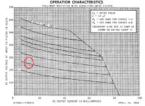
The circuits look to operate the triodes at plate voltages around half the HT supply voltage. An HT of 250V, for example, suggests that the triodes are set up to operate at approximately 1mA. Counting the phono cascode as a single triode for this purpose of counting stages the current draw of the stereo pre-amp is around 8mA, plus the current flowing through the potential divider used to generate the heater elevation bias we’re not going to be far from a 10mA current draw. For the phono amp it seems reasonable, but for a line amp with CF output it seems rather light.
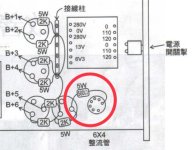
The psu uses a 6X4 rectifier and data sheets suggest a lower input capacitance than is shown in the M7 & M77 schematics. Hence the need for additional series resistance and the use of well made rectifier tubes.
The circuits look to operate the triodes at plate voltages around half the HT supply voltage. An HT of 250V, for example, suggests that the triodes are set up to operate at approximately 1mA. Counting the phono cascode as a single triode for this purpose of counting stages the current draw of the stereo pre-amp is around 8mA, plus the current flowing through the potential divider used to generate the heater elevation bias we’re not going to be far from a 10mA current draw. For the phono amp it seems reasonable, but for a line amp with CF output it seems rather light.
The psu uses a 6X4 rectifier and data sheets suggest a lower input capacitance than is shown in the M7 & M77 schematics. Hence the need for additional series resistance and the use of well made rectifier tubes.
Attachments

Member
Joined 2009
Paid Member
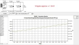
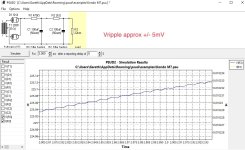
I’ve taken some of the values from the schematics and run PSUD simulations to see if they make sense.
The HT voltages look to be around 225V and 250V for the M7 & M77 respectively (simulated at the point before the parallel RC filters). With ripple voltages that are +/- 5mV and +/- 3mV respectively. The Japanese magazine shows a higher plate voltage at the rectifier of course with a correspondingly higher HT supply voltage.
The HT voltages look to be around 225V and 250V for the M7 & M77 respectively (simulated at the point before the parallel RC filters). With ripple voltages that are +/- 5mV and +/- 3mV respectively. The Japanese magazine shows a higher plate voltage at the rectifier of course with a correspondingly higher HT supply voltage.
Attachments
Member
Joined 2009
Paid Member
The philosophy is clearly one of using a relatively traditional PSU design, relying on RC filters to control ripple. The Audio Note UK guys went a different way, using voltage regulated HT supplies (which I've looked at in some detail) starting with series and more recently shunt style.
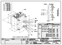
I'm going to follow the traditional non-regulated path for my HT supply design. This means that I need a transformer that will mount horizontally on the chassis and I like to get my stuff from local supplier Hammond. They call their horizontally mounting transfers the 'Z mount style' and there isn't an exact match to what I want to reproduce the M7 supply. Nevertheless, for the closest in size and weight with usable specifications I'm going to use the 273AZ power transformer.
The HT is higher than I need but additional resistance in series with the rectifier will both reduce the rectified voltage and further reduce the peak stress on the supply. So I think the direction for the HT PSU is settled.
Attachments

Last edited:
Really nice metal work! Looking forward to your assessment when it is up and running. There seems to be something special about the sound of 6072. I have made sort of a clone (of a clone?) of the Shindo Claret linestage that Thorsten Loesch published some years ago and I'm loving it. It's simply a great preamp. Those old guys from Japan knew their stuff.
Member
Joined 2009
Paid Member
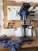
Thanks for the kind words! Hope you didn’t mistake the photos of a real M7 as being my build though ! The challenge with most things is getting enough practice with your tools, whether fancy or basic. And without a cheap drill press from Canadian Tire, I would have struggled.
(I’ll share my Claret build once this one is finished)
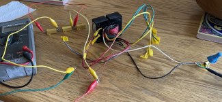
I’m looking at the heater supply now. I’m going to need to modify the transformer to get what I need by adding some extra turns. Nothing too fancy needed for this, thankfully. And I have some suitable 22 swg magnet wire so I wound 7 turns around the core and powered it up. The unloaded AC voltage was equivalent to 0.19 V/turn. Looking at the spec sheet the unloaded voltage needs to be higher than the rated loaded voltage by an amount that depends on various details but is in the range of 10%.
This gives me useful information for designing extra windings.
(I’ll share my Claret build once this one is finished)
I’m looking at the heater supply now. I’m going to need to modify the transformer to get what I need by adding some extra turns. Nothing too fancy needed for this, thankfully. And I have some suitable 22 swg magnet wire so I wound 7 turns around the core and powered it up. The unloaded AC voltage was equivalent to 0.19 V/turn. Looking at the spec sheet the unloaded voltage needs to be higher than the rated loaded voltage by an amount that depends on various details but is in the range of 10%.
This gives me useful information for designing extra windings.
Attachments
Last edited:
So true.The challenge with most things is getting enough practice with your tools, whether fancy or basic.
This is getting better and better.(I’ll share my Claret build once this one is finished)
Many DIY'ers seems to think that cathode followers and feedback must be bad. It simply isn't if it is done right.
Member
Joined 2009
Paid Member
I think there were some commentators that gave the CF a bad name and then once that had been said everyone was wondering if there was a problem and sooner or later they thought they were able to hear the problem for themselves. Of course, some folk simply implemented them wrong. But you have to consider the load as part of the implementation because a wimpy CF is fine if it's lightly loaded.
Last edited:
Member
Joined 2009
Paid Member
So, I decided to add a heater winding for the rectifier. Looking at the transformer spec sheet it seems that the unloaded voltage should be 5% to 10% higher than the loaded voltage and I can expect 190mV / turn unloaded. Preferring to be on the lean side with the heater voltage I opted for 34 turns.
I measured the need to use roughly 17cm/turn so cut off about 6m of wire from the spool.
There’s half the length of wire to pull through the remaining lamination window of the bobin by starting in the middle of my 6m piece of wire, so I pulled half the wire through the window and secured it to the centre of the bobin with kapton tape. Then I pulled and wound 17 turns on half the bobin using up half of the wire. Repeating that with the other half completes the full 34 turns, covering the bobin.
Carefully powering up and using some metal jacket 25W 10Ohm resistors I measured the AC voltage under load. Of course the primary and core were not loaded by the other secondary windings but the results of this test should be indicative. What I got was:
no-load 6.52Vac, zero current
20R load 6.4Vac, 0.32A
10R load 6.3Vac, 0.63A
5R (10R x 2 in parallel) 6.15Vac, 1.23A
I think this is close enough that I’m not going to bother to tweak the number of windings. So I painted the windings with varnish and left the transformer to dry.
Attachments

Member
Joined 2009
Paid Member
No, if I wanted to do all that I’d rather just buy a finished unit from Audionote Japan because the cost wouldn’t be worthwhile for a DIY unit that has poor resale value whereas the commercial unit will have some resale value along with warranty and all the rest. As I noted above, I’m more into DIY than off the shelf stuff for items that I‘m interested and able to make. I will be looking to use good quality parts. Also, they don’t make exactly what I want, so I’m going to do it my way.
Member
Joined 2009
Paid Member
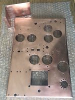
After much hole-cutting the shelf is looking like some kind of abstract artwork! There are holes for caps, tubes and for various ways to hold all the electronics together. It doesn’t match up with the M7 because mine will be mono with different parts but as with the original the power supply is up near the front plate, the line amp near the input selector and the phono amp near the phono input RCA’s. It looks about right when I drew it out.
I then cleaned it all up with some wire wool. Copper goes dull over time so I over sprayed it with some Shellac on account of finding some in my garage.
The transformer varnish is dry on one side, still waiting for it to all dry properly.
I then cleaned it all up with some wire wool. Copper goes dull over time so I over sprayed it with some Shellac on account of finding some in my garage.
The transformer varnish is dry on one side, still waiting for it to all dry properly.
Attachments
Member
Joined 2009
Paid Member
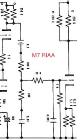
M7 RIAA
I want to look at this phono amp to see how the designer had planned it.
The schematics I’ve found for both the M7 and M77 are the same, but I noticed a small difference in the version published in the Japanese Magazine with an additional 150k resistor in parallel with the 33k, for an effective resistance of 27k instead of the 33k in the other schematics.
Attachments
Member
Joined 2009
Paid Member
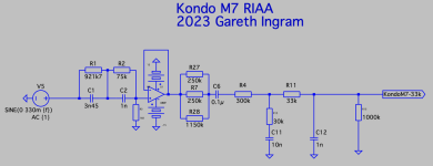
Time to run a little LTSpice on the RIAA.
I've used a standard inverse-RIAA circuit buffered by an op-amp to provide the test signal. But a low output impedance drive into the RIAA filter is not correct, you need to look at the original circuit to see that the RIAA network is being driven by a tube. The 6072 presents a plate impedance of around 1,150k in parallel with the plate load resistors which is a pair of 250k resistors in parallel.
The RIAA network is then copied out of the posted schematics. I also set up a Spice circuit for the version from the magazine which uses the extra 150k resistor in parallel with the 33k of the original schematic.
Lastly, I set up a third version of the circuit in which the 33k resistor is replaced by a 50k resistor.
Attachments
Member
Joined 2009
Paid Member
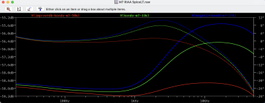
What I find is that these circuits simulate with rising treble responses both the original M7 tube schematic (green line in the plot above) and the version from the magazine (blue line) with an almost 3dB rise by 20kHz. This upper rise has been observed by other clone makers.
It's readily fixed in the simulation by increasing the value of the 33k resistor to 50k (use of nearest value or multiple resistors) which flattens the RIAA curve to produce a very good result.
What did Kondo intend here ? I've not built this schematic yet so I don't know how audible it is, or whether it's compensated for by other aspects of the pre-amp, or whether in fact tuning it by ear this response was deemed desirable. I'm also not sure whether it was intended to be used with a step-up-transformer (SUT) and MC cartridge or an MM cartridge, where loading can impact response. Was the RIAA voiced to suit a Kondo designed cartridge, arm and turntable?
There are too many variables to know.
Last edited:
I suggest you build it with the 33k as shown on the M7 schematic. After it’s up and working, measure the RIAA both ways—-with just the 33k and with the 150k in parallel—and see which has the flatter response. It’s easy to solder the 150k in parallel without altering the original build.
Member
Joined 2009
Paid Member
After looking at the M7 and M77 for awhile now I'd like to look at the current M7 offering from Audionote to see if there's some further inspiration for my build.
The latest version is the M7H
The new suffix meaning Heritage version. I'm not keen on the new chassis shape but they've used the extra space to expand a bit on the power supply and perhaps some of the ideas maybe be applied to my build.
From their website:
"Rectification tunes is 6CA4 [spec. says EZ81]. The power transformer and chokes are arranged so that minimum vibration is obtained. 3 kinds of decoupling capacitors are selected for well balance of tonal characteristics. Power supply is strengthened by clearly separating the ripple filter capacitors and decoupling capacitors.
Combining capacitor groups and a newly developed shunt type DC heater power supply circuit, ripples at power line is highly eliminated and heater voltage is regulated within ±5%."
The lineamp hasn't changed much but the phono is a different beast altogether, based on SRPP architecture.
From their website:
"The modularization of the phono amplifier realizes advantages of both handwiring and short signal paths comparable to PCB. The signal loop is minimized by placing a decoupling capacitor near the module independently.
The SRPP circuit of ECC803S (12AX7) are adopted for the first stage. 6072 (12AY7) are used for plate follower, cathode follower of the second and the third stage."
Things have changed.
Attachments

Last edited:
Member
Joined 2009
Paid Member

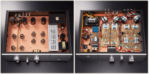
The M7H layout is very nice with neat and compact wiring. My DIY phono preamp is a rats nest by comparison.
I suspect the resistors shown in your photo are custom made by AN. I haven’t ever seen any like them before, and they look similar to the custom AN coupling caps.
The M7H no doubt sounds very good but I am skeptical about the change in phono topology. I have little interest these days in 12ax7 circuits.
- Home
- Amplifiers
- Tubes / Valves
- Build of Kondo M7 -> Kondo-Ashizawa M7H -> G-1000 & GE-10 upgrade