attenuation at the output:
e. g. paralell a 10k res to your 10k pot - this gives you a "5k pot load" similar to the original schematic and decreases the output signal.
e. g. paralell a 10k res to your 10k pot - this gives you a "5k pot load" similar to the original schematic and decreases the output signal.
Attachments

Last edited:
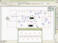
r3 100k is only for sim purposes (e. g. input impedance of an amp.......)
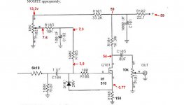
annother option......if you build in a 820 ohm res instead the 1k drain res (or
paralell a 4,7k res to the 1k ) the gain will decrease.......(around 4 x)
annother option......if you build in a 820 ohm res instead the 1k drain res (or
paralell a 4,7k res to the 1k ) the gain will decrease.......(around 4 x)
Last edited:
.....and at last.......lower r12 (10k) to 4,7k or so..... attenuates the signal a bit.......this is a little bit crude, but it helps.
(or you try out to change r3 at the output with 4.7k .......)
(or you try out to change r3 at the output with 4.7k .......)
Attachments
Last edited:
I suppose that your r3 is useless in my BoZ I'll change and listen until I get to the best sound. Thank you for your help 🙂
i guess the boz was hot......
are the voltages in the normal region when the boz is cooled down?
(all transistors in the boz need a proper heatsink!)
are the voltages in the normal region when the boz is cooled down?
(all transistors in the boz need a proper heatsink!)
voltages are the same when it starts and after few minutes.(3.0 on beginning , 3,4 after few minutes) Heatsinks of course are installed. Irf on this channel is colder than the other.The same r104(1K)
Last edited:
.......yes, the current is low.....less heat.
the boz has only a few parts to measure, so check every res (ohm) with your dmm......
is the 100uF (c102) electrolytic cap built in the right way?
if they all are correct, search for a bad soldering point/lost connection.
......and the 1uF input cap not to forget......
the boz has only a few parts to measure, so check every res (ohm) with your dmm......
is the 100uF (c102) electrolytic cap built in the right way?
if they all are correct, search for a bad soldering point/lost connection.
......and the 1uF input cap not to forget......
Last edited:
I'll check. Now I have p102 on max and bias is 2,8v if plugged in rca with CD but wihout rca it's 5,0v. Second channel still 5,6v. Caps are in good direction.
I found- R105 is ca. 70k but I'm 100 % sure that it was correct 100k
I found- R105 is ca. 70k but I'm 100 % sure that it was correct 100k
Last edited:
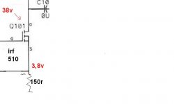
wow. There is 2,9v on input before 1u.there are 1u/400v jantzen audio. what kind can I replace? maybe some bigger for example 3u3?
.......you mean 2,9V on the node 6,2k and 100K (without cd-player connected)?
1uF is big enough i think , this gives you low pass frequency lower than 2Hz....
1uF is big enough i think , this gives you low pass frequency lower than 2Hz....
Yes, I unplugedd CD an 2,9v was on rca in. I soldered it out - there is 10Mohm on cap. Now all points measured looks ok ,
I am concerned about that problem with cap-what was the cause of damage becouse everthing was ok
I have replaced the damaged jantzen cap with a cheap replacement and now all voltage values are stable.I am concerned about that problem with cap-what was the cause of damage becouse everthing was ok
- Home
- Amplifiers
- Pass Labs
- Bride of Zen, Bride of Son of Zen