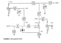
....if your source res is 150 ohm........source current is 6V/150 = 40mA;
40ma x 1k = 40 V drop across the drain res..........
16V + 40V = 56V , this should be your drain voltage at the res psu side.
you can decrease the current a little bit ( 36mA or so)
and/or use a lower value for the 1k res (e.g. 820 ohm) to get the 20V from
the schematic.......
40ma x 1k = 40 V drop across the drain res..........
16V + 40V = 56V , this should be your drain voltage at the res psu side.
you can decrease the current a little bit ( 36mA or so)
and/or use a lower value for the 1k res (e.g. 820 ohm) to get the 20V from
the schematic.......
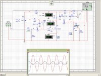
Now I have 57,5 , 21,5 and 5,2 -everything looks ok. Now I'm waiting for few power resistors to try to reduce the gain through decrease resistor 104.I want to check the results on the oscilloscope. Any case, thanks for your help in my first attempts in DIY
Everything looks good but I measured the temperature on the resistor r104 and there is 70 degrees Celsius- not too much?Btw, I found that my DAC had DC on output (70mV and 135 mV) Maybe that was the cause of the damage input cap.
yes, the power res (and the transistors) warm up (if the data sheet says : power rating 3W @70 deg. celsius, it is ok)......
.......as said before, the BOZ is a "hot bride".......needs some cooling.
.......as said before, the BOZ is a "hot bride".......needs some cooling.
Last edited:
Now I installed parallel 2 resistors and I have 847 Ohms (R104). there are Dale Cf3 3W but now the temperature on them reaches up to 100 degrees C.
I biased up and down 5,2 - 6.0 V to check the difference in sound. Res is 847 Om (1k8 and 1k6 in paralell)
if your source res is 150 ohm.......with 6v drop you get 40mA draincurrent.
40mA x 847 ohm = 34V drop on the drain res and 1,36W power dissipation in total...........
40mA x 847 ohm = 34V drop on the drain res and 1,36W power dissipation in total...........
I still hear music (very quiet) in the speakers although the pot is at a minimum. Can I decrease gain more? Now it's 5,6 (847R/150R) and bias 35mA
if there is a 10k pot at the output,.......see post 81;
the ground lines(wire) from the pcb to the pot ground tap should have low
resistance, that means: keep them short and use a proper diameter (0,22qmm and bigger).
the ground lines(wire) from the pcb to the pot ground tap should have low
resistance, that means: keep them short and use a proper diameter (0,22qmm and bigger).
I have pararel 10k with the potif there is a 10k pot at the output,.......see post 81;
the ground lines(wire) from the pcb to the pot ground tap should have low
resistance, that means: keep them short and use a proper diameter (0,22qmm and bigger).


fiddle with P102 to get 4V at mosfet source , ref. to gnd
that's sole important setting , everything else is secondary
I do not agree with this completely
The problem with my BOZ was the volume control on the output combined with the asymmetric setting of Vd (20V with 60V supply). I am sure Mr. Pass did the to find sweet spot on distortion, but it had some issues:
The gain is close to 18dB (4x) and with a CD input of 2Vrms, the output will be 8Vrms. This is almost 23Vpp and the output will be clipping on the low part, independed on volumen setting.
There are some options to prevent this:
1. Move volumen control to input, but remain 5k load on output
2. Reduce drain resistor from 1k to 750R, maintaining 40mA current but giving half supply at drain and lower gain...
3. Adjust bias for 30V drain voltage and thereby reducing drain current to 27-30mA...
2 and 3 will give new operating points and will perhaps results in increased distortion compared with original.
1 will make circuit noise independed of volumen setting...and remember that PSRR is close to 0dB
I spotted a Cree silicon carbide mosfet that other than being in the larger package might be a good substitute for our trusted irf610. The capacitance values are about the same with a power rating about 40% higher. They do however cost about $3.50 each from mouser. I wonder if they would have less distortion.
https://www.mouser.com/datasheet/2/90/3m0280090d-838555.pdf
https://www.mouser.com/datasheet/2/90/3m0280090d-838555.pdf
I reduceed gain by R104/R108 to 840R/150R
Bride of Zen, Bride of Son of Zen
Hi ! thanks so much for the very kind and valuable advice.
Just to be precise in my unit the volume pot is placed at the input ... i prefer a constant impedance output and a Zout=1K is fine for me 😉
I have still some doubts: 😕
1) i understand that the overall gain is set by the ratio 104/108 ... but i do not know the exact formula to calculate the gain. Do you know it ? 😱
2) in the original the mosfet Vds=16V ... why not decreasing the Vsupply from 60 to 40V and use a R104=500 ohm and leaving all other parts unchanged ? 🙄
Thanks again and kind regards,
gino
Attachments
Last edited:
- Home
- Amplifiers
- Pass Labs
- Bride of Zen, Bride of Son of Zen