R107 is the input impedance setting resistor.
The sch shows 100k.
What resistor are you talking about?
What schematic are you using?
The sch shows 100k.
What resistor are you talking about?
What schematic are you using?
Of course i'm comparing originaly schematic from passdiy with received BOZ . In R107 two resistors are installed in parallel and their value is together 1,5k.Qustion is good idea changing back to 100k like on schematic?
my measured values
An externally hosted image should be here but it was not working when we last tested it.
Attachments
Last edited:
fiddle with P102 to get 4V at mosfet source , ref. to gnd
that's sole important setting , everything else is secondary
that's sole important setting , everything else is secondary
Those numbers don't compute (stolen from another Thread)
3.6V across 100r gives 36mA
(59-17.6) = 41.4V across 1k0 gives 41.4mA
5.4mA has gone missing?
3.6V across 100r gives 36mA
(59-17.6) = 41.4V across 1k0 gives 41.4mA
5.4mA has gone missing?
Ok. 🙂 what about r107?There is 1k5fiddle with P102 to get 4V at mosfet source , ref. to gnd
that's sole important setting , everything else is secondary
R107 is isolated from the bias/DC conditions on the FET.
All it does is demand excessive current from the Source.
Have you found an explanation for the missing current?
You need to bias up the FET correctly.
All it does is demand excessive current from the Source.
Have you found an explanation for the missing current?
You need to bias up the FET correctly.
And what about this?other diference: in Q1 there isn't tip29- there is c2073. It's good replacment?
I didn't change anything just set bias to 4v. now I have 57v before r104 and 13,6v after it.R107 is isolated from the bias/DC conditions on the FET.
All it does is demand excessive current from the Source.
Have you found an explanation for the missing current?
You need to bias up the FET correctly.
with one-line posts , I'm still not getting what problem is
invest some effort to present entire situation and then we can help
invest some effort to present entire situation and then we can help
Sorry for my english🙂I got the BoZ that was made ca. 10 years ago. I wanted to exchange resistors for the better and I noticed that there are differences in relation to the original scheme. I try to find out why there are such differences and whether they do not affect the whole preamp. The differences are also in measured voltages.
that's easy - just follow schematic and change whatever is not by schematic
resistors are cheap , and this way is easier than thinking about every position
resistors are cheap , and this way is easier than thinking about every position
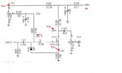
Ok,this is how the BoZ scheme looks at the moment. Questions:What happens when I change R107 to 100k? I'm afraid to destroy something.
Are the voltages that I have measured acceptable? R104 is composed of three parallel resistors that are very hot, they can not be touched - it's problem?
Are the voltages that I have measured acceptable? R104 is composed of three parallel resistors that are very hot, they can not be touched - it's problem?
Attachments

R107 is separated from the input device by the DC blocking capacitor.
It does not load the amplifier's input.
Increasing R107 makes for an easier load on the Source.
It should never have been 1k5. Put it back to 100k.
And add some RF attenuation to the input.
0.1nF NPO, or Polypropylene across the 100k.
It does not load the amplifier's input.
Increasing R107 makes for an easier load on the Source.
It should never have been 1k5. Put it back to 100k.
And add some RF attenuation to the input.
0.1nF NPO, or Polypropylene across the 100k.
- Home
- Amplifiers
- Pass Labs
- Bride of Zen, Bride of Son of Zen