Don’t stop from experimenting, but generally, if Bob Cordell says “I’d never do this”, you may want to genuinely ponder why you’d want to try differently... 🙂 🙂 🙂
But....but.......but.......
Bob in fact says "I would almost never......."
He doesn't say “I’d never do this”
I might be splitting hairs but I'm just quoting directly.
t
Bob in fact says "I would almost never......."
He doesn't say “I’d never do this”
I might be splitting hairs but I'm just quoting directly.
t
this is an unsupported modification of Bob Cordell's design and NOBODY supports it. NO BODY. Nobody answers questions about it. Nobody helps people who can't get it to work
You are on your own, kiddo. Proclaim it proudly. Best wishes for flawless success.
Maybe you could whine and wheedle and pester Bob Cordell into offering his opinion about your ideas, but that would be a little tawdry IMO.
_
Last edited:
"Maybe you could whine and wheedle and pester......"
Mark Mark Mark......
I'm not sure your choice of words is appropriate.
I've tried to keep my enquiries light hearted and it would be nice if replies were in the same manner.
tim
Mark Mark Mark......
I'm not sure your choice of words is appropriate.
I've tried to keep my enquiries light hearted and it would be nice if replies were in the same manner.
tim
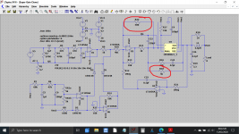
One trick you could experiment with is altering the noise gain.
The chip is stable from gains of 10 upward and so we have to trick the chip into thinking it is running at higher gain when it in fact (for your wanted signal) it isn't.
We do that be adding one resistor between the two inputs. Lets say we want a signal gain of just 5.
The chip now thinks it sees a feedback network of (in this example below) of 5k and 1k as far as signal goes, and that gives us a signal gain of 5000/1000 which is just 5.
That's OK for our signal but way below the minimum gain requirement of the chip. So we add another resistor between the inputs, in this case 500.
The chip now see a 'noise gain' feedback network of 5k (the feedback resistor) and now the 1k is in parallel with our newly added 500 ohm resistor.
How does that work? Well the 500 ohm sees no signal across it because both inputs are effectively at ground potential. So now the feedback network (for noise gain) gives a value of 5000 divided by the equivalent parallel value the two resistors. The 1k and 500 in parallel equate to a single 333 ohm.
Now we get a noise gain of 5000/333 which is 15. The chip is happy as we are comfortably over the minimum of 10.
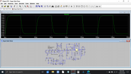
Does it work? Yes, it works really well and here is a squarewave test of the amp configured in this way. Squarewave testing is really revealing of stability.
If we remove the 500 ohm we can see just how unstable (as expected) the amp has become (last image).
The chip is stable from gains of 10 upward and so we have to trick the chip into thinking it is running at higher gain when it in fact (for your wanted signal) it isn't.
We do that be adding one resistor between the two inputs. Lets say we want a signal gain of just 5.
The chip now thinks it sees a feedback network of (in this example below) of 5k and 1k as far as signal goes, and that gives us a signal gain of 5000/1000 which is just 5.
That's OK for our signal but way below the minimum gain requirement of the chip. So we add another resistor between the inputs, in this case 500.
The chip now see a 'noise gain' feedback network of 5k (the feedback resistor) and now the 1k is in parallel with our newly added 500 ohm resistor.
How does that work? Well the 500 ohm sees no signal across it because both inputs are effectively at ground potential. So now the feedback network (for noise gain) gives a value of 5000 divided by the equivalent parallel value the two resistors. The 1k and 500 in parallel equate to a single 333 ohm.
Now we get a noise gain of 5000/333 which is 15. The chip is happy as we are comfortably over the minimum of 10.
Does it work? Yes, it works really well and here is a squarewave test of the amp configured in this way. Squarewave testing is really revealing of stability.
If we remove the 500 ohm we can see just how unstable (as expected) the amp has become (last image).
Attachments

Forgive me if I missed this earlier, but... What is the difference in the performance of the super gain clone and the compact 3886? I was just looking at the parts on Mouser and they are missing a 1k resister that won't be in for a few weeks. Digikey lists it as a special order with a 5 month turn around. And the compact is missing an LED which shouldn't be hard to source. Of course, I bought both boards and 2 PS boards so I can ultimately build both. Just curious at this point. Thanks!!
Bob
Bob
Hi,
Has anyone produced a super gainclone circuit I could etch at home? I haven't made anything for a while, but have most of the components already.
Thanks
Richard
Has anyone produced a super gainclone circuit I could etch at home? I haven't made anything for a while, but have most of the components already.
Thanks
Richard
Last edited:
Hello,
what could I use instead of LM833N ? I know that mouser have plenty of it but I have to order somewhere else 🙁
TL072IP is ok ? NE5532 ?
what could I use instead of LM833N ? I know that mouser have plenty of it but I have to order somewhere else 🙁
TL072IP is ok ? NE5532 ?

I'm going to beg to differ here and say that the TL072 (not a TL071 which is a single opamp) would be fine. Those series resistors internal to the chip are within the overall feedback loop which is applied externally.
I like the TL0 series and they can be capable of excellent sonics.
The LM833 is another excellent device but be aware that two versions exist, the old original device and a revamped version with a quasi complementary output stage (imo the one to go for).
About op-amps use.
I like the TL0 series and they can be capable of excellent sonics.
The LM833 is another excellent device but be aware that two versions exist, the old original device and a revamped version with a quasi complementary output stage (imo the one to go for).
About op-amps use.
Thanks Mark and Mooly.
Actually the LM833P is available but as it is 0.7$ -> 4.5 $ I was thinking I missed something.
I have TL072 and NE5532 in stock, I will try.
Actually the LM833P is available but as it is 0.7$ -> 4.5 $ I was thinking I missed something.
I have TL072 and NE5532 in stock, I will try.
The chip used for the Klipper part of the circuit shouldn't really have any impact on sonics and the same applies to the chip used for the servo, however the servo opamp should definitely be a FET type such as the OPA134 listed or a TL071 (the single). Both those are perfect for servo duty.
@ Tripmaster
There are quite some versions around. If you have a professional etching system at home, maybe heated foam or the like, do your own. In any other case, buy it finished. Where i live, I can´t even get good photo coated PCB material for the price you pay for a PCB on ebay or Aliexpress.
There are quite some versions around. If you have a professional etching system at home, maybe heated foam or the like, do your own. In any other case, buy it finished. Where i live, I can´t even get good photo coated PCB material for the price you pay for a PCB on ebay or Aliexpress.
Hi Mark,
As I read this thread, I noted the reference to PCB's by P. Daniel. I have some LM3875 and 4780 chips. Is it OK to use the chip amp PSU from the GB for these chips?.
MM
As I read this thread, I noted the reference to PCB's by P. Daniel. I have some LM3875 and 4780 chips. Is it OK to use the chip amp PSU from the GB for these chips?.
MM
As long as you use a 200 VA transformer or less, AND as long as you keep the DC voltages comfortably less than the max-V rating of the electrolytic capacitors you buy, then you can use the "PSU for Chipamps" PCB (which has its own thread on diyAudio).
Make a list of eight possible explanations. I'm sure your list will contain the one that I'm thinking of.
- Home
- Amplifiers
- Chip Amps
- Bob Cordell's Super Gain Clone PCB (LM3886) and a stripped-down version: Compact3886