Tim applied several changes to his SGC PCB and none of them helped. Eventually that board became unusable due to multiple rework operations. Could have been lifted copper pad, broken track, I don't remember. Then he built a second SGC PCB on a brand new board, with brand new components and a tiny circuit modification I suggested. The second board made no pops either at turn-on or turn-off. But he never removed the mod on the second PCB to see if the pops would return. So we don't actually know whether the problem was simply an error or bad component on the first PCB, which disappeared when he threw that board away and built the second PCB.
To apply the tiny mod, you must first measure the DC voltage of the two power supplies at the inputs to the SGC board (labeled "+IN" and "-IN" on the silkscreen), with both the PSU and the SGC board(s) mounted in the chassis. Tim was using a transformer with unusually high secondary voltage (and correspondingly larger heatsink), as I recall. I doubt that his measured voltages would match anybody else's.
Also, Tim had the good fortune to live in an Australian city with a Jaycar retail store, so he could buy electronic components and solder them in, an hour later. Not everyone is so lucky!
Mark,
I checked the +/- voltages on both boards and I'm getting an almost perfect mirror at 30.45V each. Measurements were don in the chassis, too.
I checked the +/- voltages on both boards and I'm getting an almost perfect mirror at 30.45V each. Measurements were don in the chassis, too.
Mark was very helpful in my quest toelminate the turn on and turn off pop.
I tried several RC combinations in the mute circuit to change the time constant.
Eventually I wired in (at Mark's suggestion) a combination with a zener (I would need to look up the details) and that fixed both pops.
I was happy.
Thanks again Mark.
t
I tried several RC combinations in the mute circuit to change the time constant.
Eventually I wired in (at Mark's suggestion) a combination with a zener (I would need to look up the details) and that fixed both pops.
I was happy.
Thanks again Mark.
t
Something like " A Complete Guide to Design and Build a Hi-Fi LM3886 Amplifier - Circuit Basics " ?
Attachments

I hope Mark doesn't mind me posting his advice.
"....... I'd recommend using ten microfarads .......... I also think I'd recommend starting with 22K in series with a 24V or 22V zener diode, in place of the 33K mute resistor."
Worked for me.
t
"....... I'd recommend using ten microfarads .......... I also think I'd recommend starting with 22K in series with a 24V or 22V zener diode, in place of the 33K mute resistor."
Worked for me.
t
Some long ovebuild pics
After installing the new components Mark suggested, my turn off pop was gone.
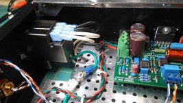
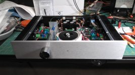
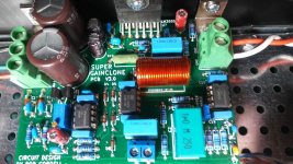
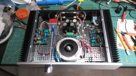
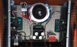
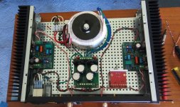
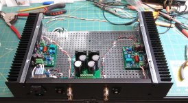
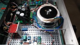
here's a few pics of the build. Imitation being the sincerest form of flattery, I pretty much copied Mark's layout with a few minor changes. I added a filtered and shielded ac inlet, a volume pot and an input terminal to the amp boards after doing some careful surgery on the back corner of them with a Dremel so they'd fit over a resistor.
After installing the new components Mark suggested, my turn off pop was gone.
here's a few pics of the build. Imitation being the sincerest form of flattery, I pretty much copied Mark's layout with a few minor changes. I added a filtered and shielded ac inlet, a volume pot and an input terminal to the amp boards after doing some careful surgery on the back corner of them with a Dremel so they'd fit over a resistor.
Attachments
-
 20200411_150023_Burst01.jpg142.5 KB · Views: 345
 -
 20200411_150135_Burst01.jpg240.8 KB · Views: 371
 -
 20200411_145939.jpg156.6 KB · Views: 388
 -
 20200411_145841_Burst01.jpg177.1 KB · Views: 676
 -
 20200409_095339_Burst01.jpg130.1 KB · Views: 670
 -
 20200408_145002_Burst01.jpg129.1 KB · Views: 679
 -
 20200407_190134.jpg116.7 KB · Views: 682
Very beautiful, congratulations! A clean and tidy layout, well executed. I really like the way you notched the shiny silver mounting plate, to give extra clearance for the AC mains power inlet. BTW your inductors are a lot nicer than the ones I've made so far.
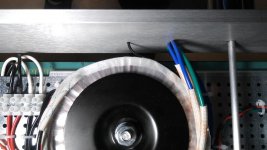
Those inductors...
Mark, thanks for the compliments! I actually did wind those inductors on a 7/16" wooden
dowel. the way I got around the softness of the wood was to put a couple of coats of water thin super glue around the length and circumference and sanding it back between each coat.that made the surface smooth and hard enough to wind the coils and still be able to slide it off afterwards.
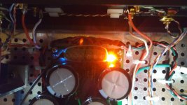
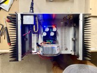
I wanted a power indicator on the front panel but I'm not a big fan of blinding blue LEDs
in that position so I came up with the idea of attaching a cheap, thin length of fiber optic
cable to the blue led on the power board using a couple different diameters of heat shrink tubing. then I merely attached it to the tranny using gorrilla tape and snaked it out the center of the front panel. hard to see the the heat shrink in the pic below but you can see how it was routed through the front. I did tie a wire strap around the output of the PS
to act as a strain relief at the LED.
Mark, thanks for the compliments! I actually did wind those inductors on a 7/16" wooden
dowel. the way I got around the softness of the wood was to put a couple of coats of water thin super glue around the length and circumference and sanding it back between each coat.that made the surface smooth and hard enough to wind the coils and still be able to slide it off afterwards.
I wanted a power indicator on the front panel but I'm not a big fan of blinding blue LEDs
in that position so I came up with the idea of attaching a cheap, thin length of fiber optic
cable to the blue led on the power board using a couple different diameters of heat shrink tubing. then I merely attached it to the tranny using gorrilla tape and snaked it out the center of the front panel. hard to see the the heat shrink in the pic below but you can see how it was routed through the front. I did tie a wire strap around the output of the PS
to act as a strain relief at the LED.
Attachments
After several impressive days of listening I decided to put it back on my scope though for a few more tests. I'll post what if anything I find as time permits.
A rod of hard plastic (acetal, nylon, HDPE, etc.) might've worked really well too. The surface would be pretty tough, and once the inductor is wound and taped, you can freeze the assembly to pull the rod out; plastic has a much higher thermal expansion coefficient than copper.Mark, thanks for the compliments! I actually did wind those inductors on a 7/16" wooden
dowel. the way I got around the softness of the wood was to put a couple of coats of water thin super glue around the length and circumference and sanding it back between each coat.that made the surface smooth and hard enough to wind the coils and still be able to slide it off afterwards.
A rod of hard plastic (acetal, nylon, HDPE, etc.) might've worked really well too. The surface would be pretty tough, and once the inductor is wound and taped, you can freeze the assembly to pull the rod out; plastic has a much higher thermal expansion coefficient than copper.
What a clever approach! Thanks for sharing it.
Another way to do is to take a section of plastic tube that is reasonably hard and stiff, for which you need to find a matching piece of steel rod or pin that fits inside the center of the tube pretty snugly (don't accept a loose slip fit). Saw out a slit lengthwise in the plastic tube, through the entire wall of one side of the tube, so that when you squeeze the tube the OD will shrink. Of course, the amount of shrink you get will depend on how wide you make the slit.What a clever approach! Thanks for sharing it.
Then, before you wind the inductor, push the metal rod into the tube to keep it from shrinking from the hoop stress of the copper winding. When done, push or punch out the metal tube and now the plastic can shrink and be pulled out.
The winding won't be perfectly round (it'll be a little "flat" across the slit) but I don't think this really affects the H. Perhaps deburr the edges of the slit in case you're worried about stress concentration in the copper during the winding process.


PF - Fantastic! Your photos are gorgeous. You inspired me to finally find a scope so I can learn how to use the Quasimodo and also set the Klever Klipper properly. 😀
PF - Fantastic! Your photos are gorgeous. You inspired me to finally find a scope so I can learn how to use the Quasimodo and also set the Klever Klipper properly. 😀
Cool!!! I'm gonna make Quasimodo T-shirts.
Still have to read up... but I think you also need a signal generator to do the Klever Klipper thing.... I did pick up the load resistors in anticipation of Klever Klippinging—one of my main reasons for wanting to make this amp... plus knowing what a "chip amp sound" is/means.
Latest SGC pdf manual contains a no-scope method of adjusting the Klever Klipper.
But, in the absence of real time measurement data, the no-scope method is forced to be rather conservative ... meaning that, in some cases, it may cause you to enter Klever Klipping a bit sooner than is absolutely necessary. You might not get those last couple of watts.
But, in the absence of real time measurement data, the no-scope method is forced to be rather conservative ... meaning that, in some cases, it may cause you to enter Klever Klipping a bit sooner than is absolutely necessary. You might not get those last couple of watts.
scope shot
Speaking of scopes, it was indeed a breeze to set up the Klipper circuit with one!
I didn't notice this when I was doing that but after letting someone with better hearing than mine check out the SGC, he said he heard something but wasn't quite sure if it was distortion or not. I put the amp back on the scope & fed it a 1khz sine wave and this is what I found. Did anyone else who built their amp and has a scope notice a small step at the crossover point?
ps; Love that chassis, PF!
Attachments

Is that the output of the amp we are looking at there? Left and Right channels.
If so then it does indeed look like crossover distortion. What is the frequency and what is the load impedance?
Also what is the voltage swing peak to peak in that shot.
If so then it does indeed look like crossover distortion. What is the frequency and what is the load impedance?
Also what is the voltage swing peak to peak in that shot.
Usually it's best to show the input and the output on the same screen. Then observers can see for themselves: error-free input, ugly output.
In this case we don't know whether the input is error-free, or not.
In this case we don't know whether the input is error-free, or not.
- Home
- Amplifiers
- Chip Amps
- Bob Cordell's Super Gain Clone PCB (LM3886) and a stripped-down version: Compact3886