You always keep the scope ground connected to the main ground on the board which is the bottom end of R1 in the original diagram in post #1.
You can then just scope (probe) the other grounds such as the speaker ground return. They should all be at the same potential and so you shouldn't see anything significant... but its just a quick check to do and confirm.
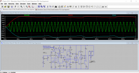
The rails are probed using that same ground reference point. Use AC coupling for the scope and see if there is any major disturbance under load. You should not see much at all in the way of superimposed signal and only a small amount of ripple.
This image is a Class AB amp with 2200uF reservoir caps in the power supply and delivering 20 volts peak into 4 ohms. You can see the ripple on each rail which is mainly 100Hz and also the signal superimposed onto it (very small).
You can then just scope (probe) the other grounds such as the speaker ground return. They should all be at the same potential and so you shouldn't see anything significant... but its just a quick check to do and confirm.
The rails are probed using that same ground reference point. Use AC coupling for the scope and see if there is any major disturbance under load. You should not see much at all in the way of superimposed signal and only a small amount of ripple.
This image is a Class AB amp with 2200uF reservoir caps in the power supply and delivering 20 volts peak into 4 ohms. You can see the ripple on each rail which is mainly 100Hz and also the signal superimposed onto it (very small).
Attachments
SGC troubleshooting
Mooly,
Thanks for the tips but for right now the SGC troubleshooting is on hold for a while as I broke a wheel mounting bolt off inside the end of the axle on my lawn tractor and of course it's blocking my car! This little nightmare has priority for now!
I'll let you know when I can get back to the amp..
I striped out a different project from my test chassis and hooked up the compact 3886 (with a slightly earlier revision PSU.) It is quiet, works and sounds fantastic, even with the less than optimal wiring and layout that used a lot of preexisting holes. 🙂 🙂 🙂
I'm very pleased.
Anybody else have one built? I'm going to build up the super gain clone as well as the compact and have them in much better looking chassis than this one.
6L6
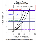
What heat sink did you use here, I am trying to figure out what size to order?
Thanks
These don’t get very hot. Basically anything that’s an amp heatsink will work. The one in the photo is about 3x9”.
Taming the LM3886: Thermal Design – Neurochrome6L6
What heat sink did you use here, I am trying to figure out what size to order?
Thanks
Thanks, 6l6, 454Casull and Mark, very helpful. I found Marks building guide after I posted my question. As always, thanks loads! you guys are awesome!🙂
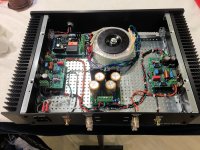
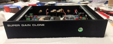
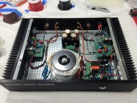
I used the wonderful Customization features of the Modushop chassis (sold through the diyAudio Store) to build a Super Gain Clone amp with customized front and rear panels. The end result is shown in the attached photos.
This is a "Dissipante 2U" chassis, it's only 88 mm tall. I downloaded the free software named Front Panel Express, watched a couple of hours of YouTube tutorials about the program, and then put in my design. It was straightforward and not at all intimidating; I encourage other diyAudio members to experiment with this software and learn about it. The price is excellent: free!
Then I sent the files (attached below) to Modushop and asked for a price quotation. diyAudio member Gianluca replied to my request very quickly, I approved the price and sent PayPal. Soon thereafter, they built and shipped my customized chassis that you see in the photos. In my opinion, the craftsmanship in this chassis is first class. And, as an extra bonus, the people at Modushop are truly a delight to work with.
To help you get started, I've attached the exact Front Panel Designer files that I created, to define this chassis. Please feel free to use it as an example of how to get things done inside Front Panel Designer. Make your own modifications and improvements; and reshape the design according to your own sense of style and imagination. Or if you wish, also please feel free to order an exact copy of the chassis you see here. You've got the files and you know they are error free. Perfecto!
I use a circular ON/OFF switch, 19mm hole diameter, mounted on the front panel. There are lots of these on eBay and DigiKey and Mouser. I happened to buy one with green illumination, but many other possibilities exist. The IEC mains inlet on the rear panel, mounts in a rectangular hole which Modushop mills out according to the dimensions in the Front Panel Designer files. The IEC inlet includes a fuse but NOT an on/off switch; that is on the front panel.
RCA jacks are the gold plated REAN NYS367 ; speaker binding posts are Parts-Express 320-3375.
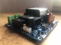
Super Gain Clone aficionados may notice an "extra" PCB in the chassis. You're right, well spotted. That's an AC mains relay board; it sends low voltage DC to the front panel ON/OFF switch, and uses that to operate a big honking relay which actually turns the amplifier's AC off and on. I did this because (a) many many of the switches I like, are only rated for 2A at 24VDC; and (b) many many of the switches I like, are MOMENTARY contact switches. Not latch-in-position action like rocker switches and toggle switches. I'll launch a thread about this board in a few days.
Finally, allow me to express my gratitude to Gianluca and the Modushop staff. Y'all made the customization procedure both simple and painless. And honestly, a lot of fun! Thank you so much.
Mark Johnson
_
This is a "Dissipante 2U" chassis, it's only 88 mm tall. I downloaded the free software named Front Panel Express, watched a couple of hours of YouTube tutorials about the program, and then put in my design. It was straightforward and not at all intimidating; I encourage other diyAudio members to experiment with this software and learn about it. The price is excellent: free!
Then I sent the files (attached below) to Modushop and asked for a price quotation. diyAudio member Gianluca replied to my request very quickly, I approved the price and sent PayPal. Soon thereafter, they built and shipped my customized chassis that you see in the photos. In my opinion, the craftsmanship in this chassis is first class. And, as an extra bonus, the people at Modushop are truly a delight to work with.
To help you get started, I've attached the exact Front Panel Designer files that I created, to define this chassis. Please feel free to use it as an example of how to get things done inside Front Panel Designer. Make your own modifications and improvements; and reshape the design according to your own sense of style and imagination. Or if you wish, also please feel free to order an exact copy of the chassis you see here. You've got the files and you know they are error free. Perfecto!
I use a circular ON/OFF switch, 19mm hole diameter, mounted on the front panel. There are lots of these on eBay and DigiKey and Mouser. I happened to buy one with green illumination, but many other possibilities exist. The IEC mains inlet on the rear panel, mounts in a rectangular hole which Modushop mills out according to the dimensions in the Front Panel Designer files. The IEC inlet includes a fuse but NOT an on/off switch; that is on the front panel.
RCA jacks are the gold plated REAN NYS367 ; speaker binding posts are Parts-Express 320-3375.
Super Gain Clone aficionados may notice an "extra" PCB in the chassis. You're right, well spotted. That's an AC mains relay board; it sends low voltage DC to the front panel ON/OFF switch, and uses that to operate a big honking relay which actually turns the amplifier's AC off and on. I did this because (a) many many of the switches I like, are only rated for 2A at 24VDC; and (b) many many of the switches I like, are MOMENTARY contact switches. Not latch-in-position action like rocker switches and toggle switches. I'll launch a thread about this board in a few days.
Finally, allow me to express my gratitude to Gianluca and the Modushop staff. Y'all made the customization procedure both simple and painless. And honestly, a lot of fun! Thank you so much.
Mark Johnson
_
Attachments

Okay. That's just awesome Mark. Beautiful job.
Really want to know more about that front power board! Slick.
Really want to know more about that front power board! Slick.
Beautifully done, Mark. Congratulations, and thank you for sharing your design and thought process. I've had some (ahem) learning moments trying to layout and cut a chassis recently. Perfectly timed.

Great design Mark, yes Modushop is outstanding they doing a great job as drilling, digital printing etc... you can also have a anodization after that all is done on the panels.
Look my On/Off switch that is inspired by APEX On/Off designed for my preamp, almost the same but with the IEC inlet who includes a fuse an on/off main switch.
That is an AC mains relay board operated by a momentary ON/OFF switch low voltage DC on the front panel , the relay turns the amplifier's AC off and on, with the command for an on/off and standby bicolor LED.
That include also a Ground Loop breaker.
I have couple of spare Board left if someone is interested, PM, you will have to pay just shipping from France.
Attachments

Beautifully done, Mark. Congratulations, and thank you for sharing your design and thought process...
Yes it is beautifully done. I'm sure Bob C would approve.
... my On/Off switch that is inspired by APEX On/Off designed for my preamp, almost the same but with the IEC inlet who includes a fuse an on/off main switch.
That is an AC mains relay board operated by a momentary ON/OFF switch low voltage DC on the front panel , the relay turns the amplifier's AC off and on, with the command for an on/off and standby bicolor LED.
That include also a Ground Loop breaker.
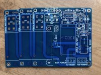
Fantastic job, good on ya! I'll be publishing the Gerber CAD files for this AC mains relay + SS board (shown in post #232), some time in the next few days. My board assumes an external IEC mains inlet and an external mains fuse (probably incorporated within the IEC inlet) so it's a little different than yours, which is great. More variety --> greater total number of happy users!
Since I knew I would be mounting the board within a Modushop chassis, I arranged my board's mounting holes to match up with the standard Modushop chassis baseplate, which has a 10mm grid of perforations. No drilling!
troystg you need to do some cleaning... your box is full i can't send you PM.Hicoco,
PM sent. Very nice work.
Fixed.. Very sorry.troystg you need to do some cleaning... your box is full i can't send you PM.
Thank MarkFantastic job, good on ya! I'll be publishing the Gerber CAD files for this AC mains relay + SS board (shown in post #232), some time in the next few days. My board assumes an external IEC mains inlet and an external mains fuse (probably incorporated within the IEC inlet) so it's a little different than yours, which is great. More variety --> greater total number of happy users!
Since I knew I would be mounting the board within a Modushop chassis, I arranged my board's mounting holes to match up with the standard Modushop chassis baseplate, which has a 10mm grid of perforations. No drilling!
There's now a thread about the "extra" circuit board pictured in post #232:
https://www.diyaudio.com/forums/pow...y-includes-soft-start-h9kpxg.html#post6216476
https://www.diyaudio.com/forums/pow...y-includes-soft-start-h9kpxg.html#post6216476
- Home
- Amplifiers
- Chip Amps
- Bob Cordell's Super Gain Clone PCB (LM3886) and a stripped-down version: Compact3886