Thanks again. I shall stick with the onboard regs! I may open a can of worms that I cant handle.
Dear Mark,
Just received my SGC order from Mouser. The DIP part supplied by Mouser matches the parts list number but they provide a 2 x 2 DIP socket. Avnet, Digikey, Arrow and RS Components all show a 2 x 2 DIP socket for the same product code, not a 2 x 4. There appears to be a problem at Mouser with their online catalogue.
Cheers
That's frustrating; I guess we'll have to switch to a different part number for a while, until Mouser corrects their problem. Worse yet, the other DIP-8 socket options at Mouser are a lot more expensive.
It appears to me that the cheapest way to get six DIP-8 sockets, might just be to buy a strip of 64 "breakaway" SIP sockets, and then break off twelve pieces of 4 pins each. Stuff one 4-pin strip for DIP pins 1-4 and another for pins 5-8. I know: that's disgusting! But at least it's cheap. The Mouser part number is
437-3108716441001101
Another option is to buy 14-pin or 16-pin DIP sockets and cut them down to 8-pins with a Dremel cutoff wheel, or a hacksaw, or a hot knife. That's also disgusting.
Another option is to buy them from somebody else besides Mouser, such as Element-14 (Newark), or Arrow, or Digi-Key, or Tayda, or Futurlec.
I am sorry Mouser has made this mistake, and would welcome any additional suggestions about workarounds, substitutions, fixups, jury-rigs, and contrivances that SGC builders could consider.
FYI, I am using in some of my designs, imo good quality a decent price for a machined contact socket.
575-1104730841001000
575-1104730841001000
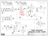
Altering the Gain
I understand he gain is set (essentially) by the ratio between R15 and R18.
The gain is currently 26dB (20x).
If I wanted to reduce the gain to, say, 20dB (10x) am I better to reduce R18, or increase R15, or a combination of both?
I guess reducing R18 increases the feedback--which may or maynot be a good thing.....I dunno
Are there any :rules" or generalisations that could/should be applied?
thanks
tim
Let's have a look at Bob Cordell's opinion. You can click on the blue arrowhead to visit the original thread where he made this post.
I would not go so far as to suggest setting the closed loop gain as low as practical. I would almost never set it below 26 dB; I see no advantage in that. Also, there is little need to set it above 30 dB for anything but really high-powered amplifiers (e.g., > 500 watts at 8 ohms). So we are really only talking about a 4 dB range in gain for most power amplifiers, which is not really a lot.
Cheers,
Bob
Thanks Mark,
unfortunately with my high sensitivity Klipschorns and 5dB preamp I have too much gain.
With my 20dB gain chip amps I only need between 12 o'clock (off) and 2pm for volume adjustment.
And extra 6db won't help.
Not necessarily the BCSGC's problem though it would be good to have all my chip amps similar as I swap between them regularly.
Maybe I'll just try 10K for R18 and see what happens.
best
tim
Repeat after me:
this is an unsupported modification of Bob Cordell's design and NOBODY supports it. NO BODY. Nobody answers questions about it. Nobody helps people who can't get it to work. It's not in Bob Cordell's book. I proudly proclaim that I am on my own.
Say it again a few times.
this is an unsupported modification of Bob Cordell's design and NOBODY supports it. NO BODY. Nobody answers questions about it. Nobody helps people who can't get it to work. It's not in Bob Cordell's book. I proudly proclaim that I am on my own.
Say it again a few times.
Attachments
Repeat after me:
this is an unsupported modification of Bob Cordell's design and NOBODY supports it. NO BODY. Nobody answers questions about it. Nobody helps people who can't get it to work. It's not in Bob Cordell's book. I proudly proclaim that I am on my own.
Say it again a few times.
Cool advice, Mark 😀!
Though not exactly the same, I have to admit that I've done a similar modification on my TI TPA3255 EVM without any issues with replacing all four opamps' feedback resistors from 10 kΩ to 20 kΩ in order to increase the module's input sensitivity 😉.
Best regards!
The Klever Klipper is a really neat idea, so simple and yet it works so well.
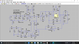
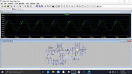
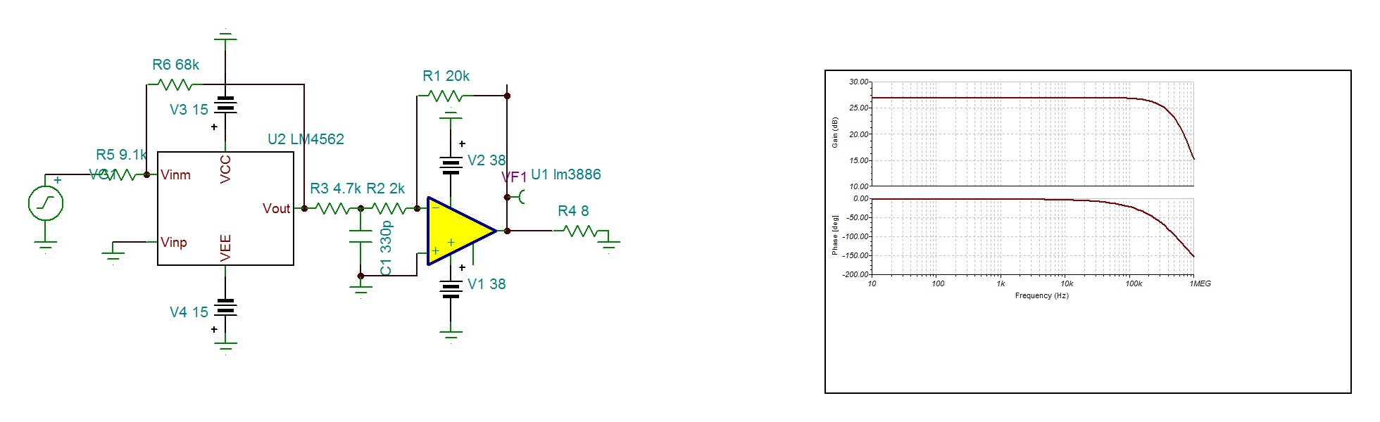
For anyone wanting to play with this circuit in LTspice I've put a file together. Don't take the LM3886 model performance to be the equal of the real thing but it does give a good insight into how it all works and you can check out the gain structure of the circuit and the Klipper.
One thing I did notice was that the servo in this circuit has a very limited pull in range and you will see I have made R12 a 600k rather than a 1meg. I'm guessing the real LM3886's have a closer input offset than my model 😀
The zipped LM3886 model file contains a folder with the .asc for the chip and the netlist and also the .asy file.
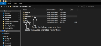
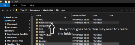
To use the model in LTXVII copy and paste the LM3886 folder into the 'Lib' folder located under Documents>LTspice and paste the symbol into a folder called 'AutoGenerated' which lives in the 'sym' folder.
(I don't know if they will transfer to different 'user name' on PC but there shouldn't be anything specific in the files. If they won't then you will have to create the model from the bare LM3886 .asc)
Enjoy 🙂 You can see the effect of the clipper in action and alter the gain to suit.
For anyone wanting to play with this circuit in LTspice I've put a file together. Don't take the LM3886 model performance to be the equal of the real thing but it does give a good insight into how it all works and you can check out the gain structure of the circuit and the Klipper.
One thing I did notice was that the servo in this circuit has a very limited pull in range and you will see I have made R12 a 600k rather than a 1meg. I'm guessing the real LM3886's have a closer input offset than my model 😀
The zipped LM3886 model file contains a folder with the .asc for the chip and the netlist and also the .asy file.
To use the model in LTXVII copy and paste the LM3886 folder into the 'Lib' folder located under Documents>LTspice and paste the symbol into a folder called 'AutoGenerated' which lives in the 'sym' folder.
(I don't know if they will transfer to different 'user name' on PC but there shouldn't be anything specific in the files. If they won't then you will have to create the model from the bare LM3886 .asc)
Enjoy 🙂 You can see the effect of the clipper in action and alter the gain to suit.
Attachments

........... Maybe I'll just try 10K for R18 and see what happens.
best
tim
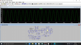
So this is how that change will affect the output voltage.
You can see my model begins to show slight instability at the lower gain setting which I think is getting toward the real lower limit of the real chip... in other words go to low with the real one and the same could happen.
Attachments
Very nice work, Mooly! Congratulations and thank you.
I suspect that changing R13 instead of R18, halves the gain with less tendency to instability. per post #130. But this is not officially sanctioned or supported.
Consider R16 and C24: should you monkey with them too, after changing R18? ugh.
I suspect that changing R13 instead of R18, halves the gain with less tendency to instability. per post #130. But this is not officially sanctioned or supported.
Consider R16 and C24: should you monkey with them too, after changing R18? ugh.
Super Gain Clone builders have discovered a problem on the detailed Parts list, with the Mouser part# of the DIP-8 sockets for the opamp chips: see posts #124 and #126 above.
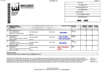
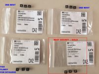
Seeking a workaround, I placed a rush order with Mouser, to try out some different part numbers and see whether they were correct and usable for Super Gain Clone builders. The answer is: all four of them are correct DIP-8 sockets, and all of them will work just fine in Super Gain Clone boards. However, one of them ("line item 002") is not a Milled Pin socket type, instead it is an Open Frame socket, and I believe it is the least attractive of the four choices. Line 002 will work. They will all work. But I wouldn't order it myself unless all three of the others were sold out or backordered or unavailable.
The one I like best ("line item 004") is a Milled Pin socket, plated with gold. The other two are also Milled Pin sockets. One is half tin, half gold; the other is all tin. Feel free to look up their prices if you worry about the cost of gold plating.
I will update the detailed Parts List, deleting the current part# that is giving people trouble, and replacing it with my two favorite sockets from today's order. I will also create a new Shared Shopping Cart at Mouser, with the new part#. I'll work with diyAudio moderators to get these attached to post #1 of this thread, as quickly as possible. And this post will serve as a photo reminder of the other two possibilities.
Mark Johnson
_
Attachments
Last edited:
By decreasing the gain of LM3886 from 20 to 3 you get 7 times less distortion. While increasing the low distorting input op amp by 7 fold , it doesn't increase much on the net result.
Attachments
Last edited:
Other than this minor detail from the LM3886 datasheet: "The LM3886 is designed to be stable when operated at a closed-loop gain of 10 or greater"
R1,R2&C1 makes a closed loop gain of 11 at high frequencies. If you can read graphs, look the stability of the circuit. By feedbacking the overall circuit , it is possible to reduce the distortion by further 50%.Other than this minor detail from the LM3886 datasheet: "The LM3886 is designed to be stable when operated at a closed-loop gain of 10 or greater"
Last edited:
Very nice work, Mooly! Congratulations and thank you.
I suspect that changing R13 instead of R18, halves the gain with less tendency to instability. per post #130. But this is not officially sanctioned or supported.
Consider R16 and C24: should you monkey with them too, after changing R18? ugh.
Thanks 🙂
R13 is definitely the safer option as regards stability as it leaves the output stage untouched. The opamp should be fine in that situation as its only really a take on a Baxandall type volume control.
Another option would be to play around with the noise gain of the LM3886 but that goes down the route of needing to check and verify all the stability margins.
One thing I did notice was that the servo in this circuit has a very limited pull in range and you will see I have made R12 a 600k rather than a 1meg. I'm guessing the real LM3886's have a closer input offset than my model 😀
This was caused by a simple error on my part in copying Marks circuit into LT. I had the servo injection point on the wrong end of R10.
Also now corrected is the use of 'QG' as a clean ground for U4B and U7 non inverting inputs.
Attachments
I will update the detailed Parts List, deleting the current part# that is giving people trouble, and replacing it with my two favorite sockets from today's order. I will also create a new Shared Shopping Cart at Mouser, with the new part#. I'll work with diyAudio moderators to get these attached to post #1 of this thread, as quickly as possible.
Done! Moderator 6L6 edited post #1 of this thread and installed the new Parts List and the link to the new Mouser Shared Shopping Cart. If you visit post #1, you will notice the change in the attachments: image below.
Thank you, 6L6!
_
Attachments

Now.....to completely beat this subject to death.....though I might learn a little
Is there any advantage (or disadvantage) to combining the two gain reducing options.
That is....reducing R20 a little--say to 18K (or even 16K) AND reducing R13 "the method-that-shall-not-be-mentioned" a balancing amount--5.5K (or 6.2K).
Almost keeps BC happy--"I would almost never set it below 26 dB"
Keeps the datasheet happy--"The LM3886 is designed to be stable when operated at a closed-loop gain of 10 or greater"
Sorta keeps Mooly happy--"my model begins to show slight instability(with R18 = 10k) at the lower gain setting" and
"R13 is definitely the safer option as regards stability"
and maybe even Kokoriantz "it is possible to reduce the distortion by further (50%)".
My idea is to add some op amp pin sockets to R18 and R13 so I can easily swap resistors and experiment.
If you see me enquiring after more BCSGC pcbs then you'll all know what happened ;>
best
tim
- Home
- Amplifiers
- Chip Amps
- Bob Cordell's Super Gain Clone PCB (LM3886) and a stripped-down version: Compact3886