I am studying, help optimize, thank you!
View attachment Figure25.14.asc
An externally hosted image should be here but it was not working when we last tested it.
An externally hosted image should be here but it was not working when we last tested it.
View attachment Figure25.14.asc
Hi hwckent,
I have the amp running nicely. I like it🙂.
See mods attached.
Cheers,
I have the amp running nicely. I like it🙂.
See mods attached.
- A VCVS is added to get "out12 = vout-1 - vout-2. It's effectively an ideal diff amp. It's needed to do FFT and .Four
- Also added Schottky diodes across Q17 etc base-collector to stop sticking when clipping.
- One split power supply (not two).
Cheers,
Attachments
Thank you IanHegglun!
This is Bob's example of A balanced amplifier without negative feedback,
I am a novice and I am learning.
This is Bob's example of A balanced amplifier without negative feedback,
I am a novice and I am learning.
An externally hosted image should be here but it was not working when we last tested it.
Attachments
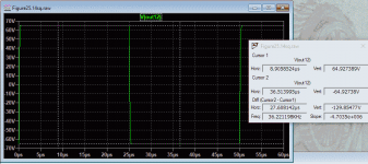
Hi hwckent,How can I optimize to make the square wave look good
I did not notice your earlier circuit had R3 as 100 ohms when it should be the same as R2 2k to match Bob's circuit.
With R2=R3=2k you get a gain of 22 requiring 2.5Vpk input. So for twice the gain I set R2=R3=1k requiring 1.3Vpk. See plot.
Next, to get a clean squarewave response I reduced 'c' to 100pF and connected input filter caps C11,C12 and increased them to 100pF.
It's clean to 65Vpk (max) and transitions 100V in about 200ns, that's about 500V/us slew rate 😱
Attachments
Thanks again IanHegglun
I should be doing it wrong, the total harmonic distortion is too high
I should be doing it wrong, the total harmonic distortion is too high
Hi hwckent,
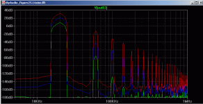
The attached gives distortion at 1W 20W and 200W

At 1W THD is 0.007% most of the distortion is from the output stage (IPS is 0.001%). At 200W most of the distortion is from the input stage 0.7%. I don't think this is a concern since music hovers around 1W on average.
Increasing the idle current from 150mA per pair to 200mA reduces 1W THD to 0.005%. But dissipation is 33% higher or 100Wpc😱 so I'd stay with 150mA.
The attached gives distortion at 1W 20W and 200W
At 1W THD is 0.007% most of the distortion is from the output stage (IPS is 0.001%). At 200W most of the distortion is from the input stage 0.7%. I don't think this is a concern since music hovers around 1W on average.
Increasing the idle current from 150mA per pair to 200mA reduces 1W THD to 0.005%. But dissipation is 33% higher or 100Wpc😱 so I'd stay with 150mA.
Attachments
Hi Bob and other forum members
Awhile ago before I build my first amplifier (The honey badger (HB)) I built one of your amplifiers on a bread board as a learning exercise.
Now, I want to measure the loop gain of my HB so I can optimise my phase and gain margins by tweaking the compensation capacitors.
To do this I wrote a python script on my computer using pycharm to control my signal generator and oscilloscope.
The script then captures all the data and generates the loop gain plots.
I then built a small op amp circuit to inject a voltage signal into the feedback path so the loop gain can be measured.
I used my breadboard amplifier to do the testing and proof of concept.
I now hope to test my HB using the same setup.
I would be interested in what you guys think.
In the plots shown I'm using a 20pf composition cap.
Hi Jan, It does seams to work. I tested it in ltspice and on the bench. I found it in a document that was linked in to a post you commented on, on the eevblog forum where from memory you show how to measure the loop gain with a injection transformer. You also showed a ltspice file and discuss the middlebrook method.Stuart, that's a very interesting way to do that measurement!
Jan
Apparently the op amp method negates the disadvantages of using a injection transformer.
See the last two pages of the attached document for details.View attachment Use Op-Amp injection for Bode Analysis.pdf
Last edited:
Hi Bob and other forum members
Awhile ago before I build my first amplifier (The honey badger (HB)) I built one of your amplifiers on a bread board as a learning exercise.
Now, I want to measure the loop gain of my HB so I can optimise my phase and gain margins by tweaking the compensation capacitors.
To do this I wrote a python script on my computer using pycharm to control my signal generator and oscilloscope.
The script then captures all the data and generates the loop gain plots.
I then built a small op amp circuit to inject a voltage signal into the feedback path so the loop gain can be measured.
I used my breadboard amplifier to do the testing and proof of concept.
I now hope to test my HB using the same setup.
I would be interested in what you guys think.
In the plots shown I'm using a 20pf composition cap. View attachment 887640View attachment 887641View attachment 887642View attachment 887643View attachment 887645View attachment 887646View attachment 887647View attachment 887648View attachment 887649View attachment 887650
Did you describe your setup anywhere else? I also have a Rigol scope and might want to
try it out if you are willing to share your scripts. What signal generator are you using?
Does the Pycharm script run on a Linux platform?
Did you describe your setup anywhere else? I also have a Rigol scope and might want to
try it out if you are willing to share your scripts. What signal generator are you using?
Does the Pycharm script run on a Linux platform?
Hi Pete,
No I haven't discussed this on any other thread as I basically just got it all working. I asked Bob back in late August about testing phase and gain margins. This is were I've ened up.
I first worked on producing straight bode plots using Vin after the input filter network and Vout measured before the zobel network.
See attached samples.
The plot has a 300pf cap installed.
Its quite tricky to capture measurements. I'm using the fine or vernier scale to maximise the scopes 8bit DAC and do math on the vertical scale to ensure my vertical scale is at about 7 divisions. You have to do a fair bit of error checking as well to ensure that you are capturing valid data.
Now moved on to measuring the loop gain using the op-amp as the injection source.
I'm now working my injection circuit to maximise my measuring range.
I hope to be able to measure from 53dB down to -23dB for a total range of 77dB
The scope and signal generator programming manuals contain all the info you need to create your script.
Pycharm suits nearly all operating systems including Linux.
While I would not share my code as it has taken many, many hours to develop. Send me a pm if you get in trouble getting your communication link going.
I'm using a Rigol DG4062 with cracked firmware to enable 200Mhz bandwidth. Its shown in my above photos. But any signal generator with programming interference should work.
These links will help you get started.
ds1054z * PyPI
Programming the DS1054Z oscilloscope in Python
I guess I love to hear what fellow more experienced forum members think of my testing methods.
Are they valid?
Can I do anything further to improve things?
I'm currently using a LME49720NA op-amp. But have a HA9P5002-5Z on order as it will give me more measuring range.


Last edited:
yes Bob, Diyaudio commissioned member Ostriper to design this amp for members to build, boards are on sale from the Diyaudio store, i built two of these and i can say this is a real good sounding amp....my only issue with this amp is that it did not have an on board SOA protection circuit...
it will be nice to hear your comments/criticisms of this amp....
it will be nice to hear your comments/criticisms of this amp....
Thank you Stuart, very nice work.
Seems it should be in a new thread so that we can find it easily.
Seems it should be in a new thread so that we can find it easily.
Hello,
Just received the new version of the book. Nice book. Going thru it quickly last night noted one thing I thought was not quite correct.
In the chapter about XD displacement (per Douglas Self) there is talk and graphs about how using two power transistors to drive the load is better than the XD circuit.
However, this is somewhat misleading as Doug in his book and his designs (Cambridge audio AZUR series) advocated using both techniques, not just one of them.
As far as I can tell from his book and articles, using both more power transistors and the SD circuit gives less distortion than either separately.
Have you looked at this combination of techniques?
Regards,
Greg
Hi Ian, you may want to watch this as your distortion plot may not be accurate as your fft resolution is to high.Hi hwckent,
The attached gives distortion at 1W 20W and 200W
At 1W THD is 0.007% most of the distortion is from the output stage (IPS is 0.001%). At 200W most of the distortion is from the input stage 0.7%. I don't think this is a concern since music hovers around 1W on average.
Increasing the idle current from 150mA per pair to 200mA reduces 1W THD to 0.005%. But dissipation is 33% higher or 100Wpc😱 so I'd stay with 150mA.
LTspice tutorial - Ep6 Basics of FFT analysis and .four statment - YouTube
- Home
- Amplifiers
- Solid State
- Bob Cordell's Power amplifier book