Opps. Sorry Ian, I ment too low. The lower the spectral resolution the wider the fft buckets are (like in your plot). The higher the fft spectral resolution is the narrower the fft buckets are, this in turn only captures data at a exact multiple of the fundamental frequency.
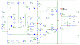
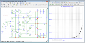
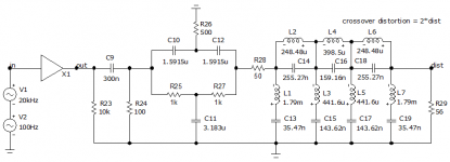
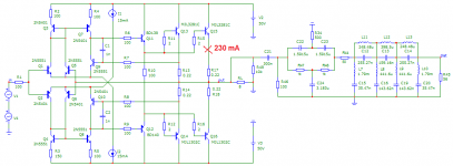
I typed a simplified model in the microcap of the Hafler HD-220 amplifier
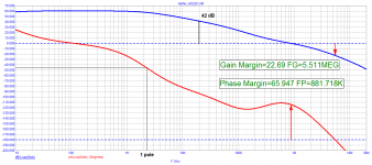
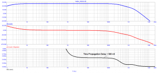
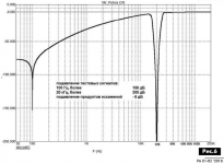
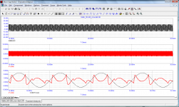
Microcap has an injector for measuring loop gain and stability margins
Here are some test results
Bob, What do you think of these tests
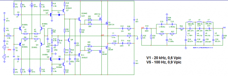
Jean Hiraga Super Class A 30w Build
Microcap has an injector for measuring loop gain and stability margins
Here are some test results
Bob, What do you think of these tests
Jean Hiraga Super Class A 30w Build
Attachments
Last edited:
I typed a simplified model in the microcap of the Hafler HD-220 amplifier
Microcap has an injector for measuring loop gain and stability margins
Here are some test results
Bob, What do you think of these tests
Jean Hiraga Super Class A 30w Build
Hi Petr,
Nice work! These plots look about right.
I wasn't quite sure about what is being portrayed in the 4th plot. Is it a SMPTE IM distortion test? Can you say a few more words about it?
Cheers,
Bob
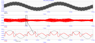
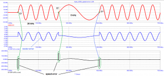
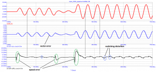
The generator signal starts working at 400 kHz and then the frequency decreases in 10% steps. The test ends with a frequency of 10 Hz.
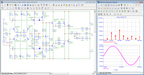
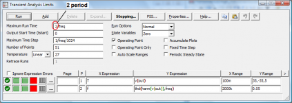
Analysis settings
The circle indicates the number of periods for each frequency. In this case, I used only 2 periods. In some amplifiers, even 10 periods are not enough due to long transient processes.
Petr
best regards
Analysis settings
The circle indicates the number of periods for each frequency. In this case, I used only 2 periods. In some amplifiers, even 10 periods are not enough due to long transient processes.
Petr
best regards
Attachments
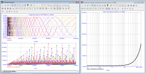
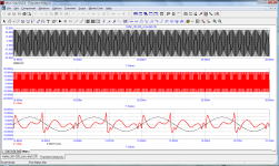
Perhaps I misunderstood which fourth drawing you are interested in if this one, then this is the result of measuring distortion using a virtual filter
Perhaps I misunderstood which fourth drawing you are interested in if this one, then this is the result of measuring distortion using a virtual filter
Attachments
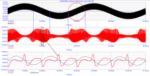


The smaller the signal amplitude, the greater the relative level of speed distortion. For example, when the signal amplitude goes from 15 V to 4 V (1 Watt, node 2), the peak value of the speed distortion is 0.25 V or 6.25%! While harmonic distortion at 20 kHz does not exceed 0.002% with an output power of 1 watt. And in node 3 it is almost three times more! And this is in an amplifier with no capacitor C1, the signal propagation delay time is only 200 ns.
Attachments
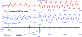
Petr, I am not Bob but try to understand this. It seems that you are taking the 2nd derivative of the signal. It is not clear to me why you call that 'distortion'; it is an inherent property of the signal.
Do you mean that this 2nd derivative is different for different amplifiers, and that this gives information about the performance of the amplifier? If that is what you mean, maybe you should take this 2nd derivative from different amplifiers and compare that.
My hunch is that the difference of 2nd derivatives between amplifiers have a lot to do with the amplifier bandwidth. Also, to judge the performance for audio, the input signal should first be run through an input low pass filter at, say, 30kHz or so.
But I may be wrong.
Jan
Jan, what about Bob? He is healthy?
Do you agree with the statement of Kyrill Hammer?
Can you distinguish the difference between distortion in steady state operation and when the signal frequency or amplitude changes?
Filter processing softens the effect of speed distortion, but does not eliminate it. If the amplifier had enough bandwidth of 30 kHz with an output voltage slew rate of 5 V / μs, then today amplifiers with a bandwidth of 5 MHz and higher would not be designed.
Personally, I agree with Kyrill Hammer and with my tests I try to show that he is right, that's all.
Attachments
The smaller the signal amplitude, the greater the relative level of speed distortion...
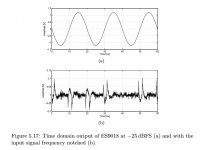
Thank you. That is very interesting. It reminds me of the problem encountered by some DAC designers, which is the ESS 'hump' distortion. A time domain capture of the distortion posted by Scott Wurcer is attached below.
EDIT: In the case of DACs and for the measurement below, although the test signal was not supposed to be changing, the DAC modulator tends to more or less randomize and redistribute the frequency spectrum of noise. Could be the ESS modulator is doing something funny at times to case a speed distortion effect in the I/V opamp.
Attachments
Last edited:
- Home
- Amplifiers
- Solid State
- Bob Cordell's Power amplifier book