The most comprehensive work I've ever seen on Headphone characterization is this list:
Headphone List - Google Sheets
Don't know who the author is but the link was given to me around 3 years ago, so it may not include the latest models. The list includes circa 500 headphone brands and models, their impedance and the required power/current/voltage to achieve 90/100/105/110/115 dB SPL, its the product of a massive ammount of work and research and its been a real eye opener for me when designing headphone amps.
Thanks! This is a tremendous piece of work, and appears very valuable.
Cheers,
Bob
I'm still reading chapter 4, about the "current limiting" in page 91. I don't understand the meaning of diodes D7, D8, D9 and D10. Firstly I though these diodes are here when overvoltage occurs but in the text I can read :"each output transistor will be limited to peak current of about 11A", how?
It interesting but some aspects are questionable. E.G. Apple earpods are Bluetooth only. How would you arrive at an impedance and sensitivity unless you cut them open? And would that be meaningful? Some of the others may be active only as well. And most of the numbers are calculated. Some of those have significant power compression (I have measured it) and it doesn't show on the chart.Thanks! This is a tremendous piece of work, and appears very valuable.
Cheers,
Bob
Still 400+ headphones!!! Not a good business opportunity.
Looks like someone checked in the measured data from InnerFidelity for all or almost all the headphones tested and then used the three values per headphone to calculate all the rest. (I would have linked but for some reason the site redirects to Stereophile now, possibly they axed it? It was never quite the same after Tyll Hertsens left to enjoy his well-deserved retirement.)
I think the most comprehensive tables I've seen to date would have to be those of reference-audio-analyzer.pro.
I think the most comprehensive tables I've seen to date would have to be those of reference-audio-analyzer.pro.
Hi Bob,
I just had a quick question regarding Stability Evaluation on page 110 of the second edition.
The book says. "Shunt R8 with a 10K resistor to increase closed-loop gain by 3 dB. Shunt the junction of
R7 and R8 to ground with a 39-pF capacitor."
Just wanted to check. Do you actually mean "loop gain" and not "closed loop gain"... so it would read.
Shunt R8 with a 10K resistor to increase loop gain by 3 dB?
I have also made a sketch. Can you confirm what I have sketched is correct.
Thanks.
Hi Stuart,
You are correct and you have found an error in the book. The shunting resistor is there to increase the feedback loop gain to make up for the 3-dB loss introduced by the LPF created by the shunting capacitor.
Thanks!
Bob
You are correct and you have found an error in the book. The shunting resistor is there to increase the feedback loop gain to make up for the 3-dB loss introduced by the LPF created by the shunting capacitor.
Thanks!
Bob
Thanks Bob,
I also wanted to check.
The book says.
"This introduces a pole and 3 dB of loss at 1 MHz"
Was that rounded up? As I caculated it to be about 700K.
Thanks again.
I also wanted to check.
The book says.
"This introduces a pole and 3 dB of loss at 1 MHz"
Was that rounded up? As I caculated it to be about 700K.
Thanks again.
Hi Stuart,
The net resistance seen by the 39 pF capacitor is the parallel combination of the resistances on the branches to the left and right of the node. On the left is 13.3k + 1k (14.3k). On the right is the parallel combination of 14.3k and 10k (5.83k). The parallel combination of 14.3k and 5.83k is 4.14k. This resistance combined with 39 pF creates a pole at 985 kHz.
Cheers,
Bob
Perfect, this now makes sense and I can apply it to other situations.Hi Stuart,
The net resistance seen by the 39 pF capacitor is the parallel combination of the resistances on the branches to the left and right of the node. On the left is 13.3k + 1k (14.3k). On the right is the parallel combination of 14.3k and 10k (5.83k). The parallel combination of 14.3k and 5.83k is 4.14k. This resistance combined with 39 pF creates a pole at 985 kHz.
Cheers,
Bob
Thanks Bob.
Hi Bob,
I have been working though the stability evaluation testing a bit more on the simulator this week and had two more question for you.
The book says "Shunt R8 with a 10K resistor to increase loop gain by 3 dB.
Shunt the junction of R7 and R8 to ground with a 39-pF capacitor.
This introduces a pole and 3 dB of loss at 1 MHz. Existing phase margin has now been reduced by 45 degrees. If the amplifier does not oscillate,
it has at least 45 degrees of phase margin. Measure the amount of peaking in the frequency response. Peaking of 3dB would suggest a phase margin of 45 degrees."
Q1. Should I run the square wave response before I connect the
39-pf capacitor ? ( Gain margin will be reduced by 3dB at this stage)
Q2. The book says to measure the amount of peaking in the frequency response. Peaking of 3dB would suggest a phase margin of 45 degrees.
Am I measuring this on the square frequency response? If not where is the peaking of 3dB measured ?
Thanks
In this context, I'm referring mainly to frequency response measurements. Looking for general indications of stability in these steps using a square wave stimulus would be an optional thing to do in addition to the frequency response evaluations.
Hope this helps.
Cheers,
Bob
Hope this helps.
Cheers,
Bob
Bob,
Thanks for the book, it's been really fun and educational.
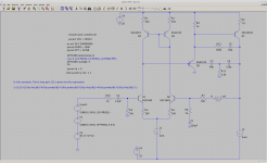
I found a nice way to tame TPC's audio-band loopgain peak, see attached.
With this approach, we don't have to degenerate the VAS if we don't want to, and we don't have to increase load on the IPS. The caveats are, this only works with a buffered VAS and it could reduce slew rate.
Here's what I suspect is going on.
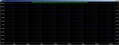
The TPC peak happens when the TPC caps "kick in" around 2kHz and pivot the VAS phase from 0 to -180 degrees all at once. At some frequency there's a deep null, where the 0 degree and -180 degree components cancel and the input needed for a given VAS output approaches zero. So we get that asymptote in the loop gain.
This fix works by having C5 add some phase lag starting at LF. When TPC takes over around 2kHz, VAS phase pivots from about -30 degrees to -180 degrees avoiding the deep null. Above 2kHz C5 has little effect, and R12 minimizes its effect at HF.
Thanks for the book, it's been really fun and educational.
I found a nice way to tame TPC's audio-band loopgain peak, see attached.
With this approach, we don't have to degenerate the VAS if we don't want to, and we don't have to increase load on the IPS. The caveats are, this only works with a buffered VAS and it could reduce slew rate.
Here's what I suspect is going on.
The TPC peak happens when the TPC caps "kick in" around 2kHz and pivot the VAS phase from 0 to -180 degrees all at once. At some frequency there's a deep null, where the 0 degree and -180 degree components cancel and the input needed for a given VAS output approaches zero. So we get that asymptote in the loop gain.
This fix works by having C5 add some phase lag starting at LF. When TPC takes over around 2kHz, VAS phase pivots from about -30 degrees to -180 degrees avoiding the deep null. Above 2kHz C5 has little effect, and R12 minimizes its effect at HF.
Attachments
It's possible that the TPC topology I mentioned above is equivalent to bridged-T.
I've had two doubts about bridged-T:
1) If you place the loopgain probe such that the traditional TPC network pick-off point and the bridge cap pick-off point are on opposite sides of the probe, there's still a peak.
2) It asks the IPS to drive a cap with the full output voltage swing on the other side, and it's the distorted VAS output voltage at that.
It turns out that (1) is true of the alternate topology as well, see attached.
To some extent, (2) is true of the alternate topology too. The IPS must drive C5. The VAS buffer hFE helps, yet C5 is >10x larger than a typical "bridged T" cap which partly cancels that benefit.
They're so similar, let's call this variant a "buffered bridge."
Attachments

A Darlington VAS has two poles and if they are too close together the VAS becomes an unstable feedback loop all by itself. The two transistors should be different speeds so that one will dominate and stabilize the local loop. The pull down resistor between the two transistors needs to be small enough to allow a decent slew rate but too small brings the second pole up near the first causing instability.
I don't like to see the first transistor without a collector resistor but the resistor needs a decoupling cap to avoid aggravating the local loop instability.
I don't like to see the first transistor without a collector resistor but the resistor needs a decoupling cap to avoid aggravating the local loop instability.
Last edited:
C5/R12 looks good in charts, but is not very useful because ultimately you are conducting distortion into the preceding stages. This means you are both increasing distortion and reducing loop gain at the same time.
Furthermore you are loading the VAS which increases it's own contribution to distortion.
If you have a good reason to need to get rid of the resonance (it MIGHT, but probably won't, matter during overload durations longer than it's wavelength), one solution is a 1pF cap bypassing both TPC capacitors, or a 10nF cap in series with the 3.3k resistor. These do not needlessly load the VAS but perform the same function.
The usefulness of the resonance as a loop gain boost is arguable as, like any resonance, it has an associated group delay and very narrow frequency range where it's effective. On the other hand, it's effect is never to increase distortion, just to reduce distortion in a limited capacity.
So to decide what to do about it, you really need to investigate whether it matters in the context of listening to music. Alas, LTspice cannot simulate humans...
Blast, the 'buffered bridge' depends on the beta of the buffer transistor. That's a problem.
keantoken, thanks, the 10nF cap in series with the TPC resistor is a cool idea. It works and it doesn't depend on any caps with 50% tolerance like some 1pF units.
Whether we use a 1pF bridge cap or the 10nF cap, either couples some distorted current from the VAS back to the IPS. Maybe it's not enough to matter, but it would be nice to avoid if we can.
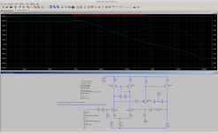
Here's another arrangement that tames the peak. C10 and R13 add another pole and another zero, both low enough that they have little effect at HF. It never pushes loopgain phase past -180 so conditional stability shouldn't be a problem.
keantoken, thanks, the 10nF cap in series with the TPC resistor is a cool idea. It works and it doesn't depend on any caps with 50% tolerance like some 1pF units.
Whether we use a 1pF bridge cap or the 10nF cap, either couples some distorted current from the VAS back to the IPS. Maybe it's not enough to matter, but it would be nice to avoid if we can.
Here's another arrangement that tames the peak. C10 and R13 add another pole and another zero, both low enough that they have little effect at HF. It never pushes loopgain phase past -180 so conditional stability shouldn't be a problem.
Attachments
Hi,A Darlington VAS has two poles and if they are too close together the VAS becomes an unstable feedback loop all by itself.
If possible, can you explain how there is a local feedback loop for the VAS ?. Thanks.
The transistors are different, so will have different parameters. Is it therefore possible, that the VAS loading circuit for the second transistor, and the first transistor, both have the same poles just by pure coincidence ?.The two transistors should be different speeds so that one will dominate and stabilize the local loop. The pull down resistor between the two transistors needs to be small enough to allow a decent slew rate but too small brings the second pole up near the first causing instability.
I don't like to see the first transistor without a collector resistor but the resistor needs a decoupling cap to avoid aggravating the local loop instability.
Also, if you implement the collector resistance for the first VAS transistor, this will have the effect of introducing a pole which can be made to be dominant. Why would you need a capacitor across that resistor to ensure local loop stability ?. Thanks.
Regards,
Shadders.
Darlington VAS
The "Miller" compensation cap becomes the feedback path from the output collector to the input base. It's a similar problem to putting a small cap across the feedback of an op-amp, ie requires op-amp be unity gain stable.
Not necessarily exactly the same pole. Just too close.
A decoupling cap on the first transistor avoids high frequency signal on that collector and therefore reduces the multiplier effect on the Cbc of that transistor, which means that pole is farther away from the second pole. A small resistor or none has a similar effect but leaves the first transistor without a current limit on clipping and drives the second transistor into hard saturation which creates rail sticking.
Hi All ,
Just wondering if someone could recommend the type of capacitor used as the miller compensation capacitor. Lets say 100pf
A part number would also be very helpful.
I'm currently using these.
338-2589-ND
Thanks.
Just wondering if someone could recommend the type of capacitor used as the miller compensation capacitor. Lets say 100pf
A part number would also be very helpful.
I'm currently using these.
338-2589-ND
Thanks.
The mica cap you have looks fine. A ceramic cap with a C0G/NP0 temperature coefficient like this will also work: 399-5100-ND
- Home
- Amplifiers
- Solid State
- Bob Cordell's Power amplifier book