JLH suggests we set up his amplifiers using our standard RF filter at the input and a variable R+C in the feedback loop. Adjust VR until the overshoot just disappears for best sound. Then replace the adjusted VR with a fixed resistor.
[snip]Adjust VR until the overshoot just disappears for best sound. [snip].
Does he imply that disappearance of overshoot leads to 'best sound'? Or is that your interpretation?
jan didden
Another thought: I appreciate that the equations in the link are only valid for second order systems, which strictly speaking, audio amplifiers aren't.
But I think a 'standard' (dare I say blameless) amplifier closely approximates to a second order system (one with two poles) - the low frequency dominant one (set by the gm of LTP and the miller cap of the VAS), and the much higher frequency output stage pole.
I have often thought of measuring the frequency response of the output stage in isolation in order to determine the frequency of the HF pole (but I have never done that in practice). In theory, I could then predict what gm and millercap are required to give a certain phase margin.
Another thought: It strikes me that the position of the HF pole varies with signal (or fast edge) amplitude, since it is not unusual to get more overshoot with large input edges than small ones.
I agree that 'real' audio signals are unlikely (never) going to produce any overshoot whatsoever, so I am often surprised by people who say they can hear the difference between (for example) a 68pF miller cap and a 100pF miller cap.
JLH tells us to adjust for no overshoot for best sound.Does he imply that disappearance of overshoot leads to 'best sound'? Or is that your interpretation?
That is not an artefact of my imagination.
Crucial to this setting up procedure could be the RF filter at the input. It appears to be a set up to suit real audio input signals.
Could removal, or widening the pass band, of the RF filter bring back some visible overshoot on fast changing (high slew rate) signals?
However, this may apply only to his range of amplifiers. I cannot decide if that could become a universal rule.
Last edited:
JLH tells us to adjust for no overshoot for best sound.
That is not an artefact of my imagination.
Crucial to this setting up procedure could be the RF filter at the input. It appears to be a set up to suit real audio input signals.
Could removal, or widening the pass band, of the RF filter bring back some visible overshoot on fast changing (high slew rate) signals?
However, this may apply only to his range of amplifiers. I cannot decide if that could become a universal rule.
Well, it's very unusual that JLH says something like that, it is a bit out of character, that's all.
Anyway, using an input filter will probably kill most of the overshoot no matter what the phase margin (depending on the filter TC of course), so it seems very strange to recommend adjusting for no overshoot WITH the filter.
Do you have a reference to his paper?
jan didden
Another thought: I appreciate that the equations in the link are only valid for second order systems, which strictly speaking, audio amplifiers aren't.
But I think a 'standard' (dare I say blameless) amplifier closely approximates to a second order system (one with two poles) - the low frequency dominant one (set by the gm of LTP and the miller cap of the VAS), and the much higher frequency output stage pole.
Indeed. So, an amplifier with two-pole compensation and lead compensation in the feedback network can be very far from the idealised second-order system. This is why Edmond still saw overshoot on a square-wave response on the two-pole + lead compensated amplifier despite it having plenty of phase margin.
As such I'm really not convinced that you need a square-wave response with no overshoot. This will only verify ample phase margin if you've got a second-order system.
Another thought: It strikes me that the position of the HF pole varies with signal (or fast edge) amplitude
Indeed it does and quite substantially so (just take a look at a power transistors' fT as a function of Ic and Vce, or its parasitic capacitances as a function of Ic and Vce); this is the main reason you need simulated phase margin to be healthy, an output zobel + inductor should provide protection against crazy load conditions.
I agree that 'real' audio signals are unlikely (never) going to produce any overshoot whatsoever, so I am often surprised by people who say they can hear the difference between (for example) a 68pF miller cap and a 100pF miller cap.
All other things being equal, changing the miller cap not only changes the phase margin, but it also changes the magnitude of the loop gain at the high end of the audio band. Hence, HF distortion will be higher with a larger miller cap (assuming the amplifier is both stable and free of parasitic oscillations in both situations, of course).
Last edited:
All other things being equal, changing the miller cap not only changes the phase margin, but it also changes the magnitude of the loop gain at the high end of the audio band. Hence, HF distortion will be higher with a larger miller cap (assuming the amplifier is both stable and free of parasitic oscillations in both situations, of course).
Hi Harry,
I agree with all your points. My amps typically give 0.005% THD20k. I very much doubt that I would be able to hear the difference if I increased the miller cap by a factor of 2 (this is just my personal view). The new, higher value of distortion is unlikely to make an audible difference (to my ears anyway).
Perhaps the people that report audible differences do not have 'stable' amplifiers or ones that are free from parasitic oscillations. Or perhaps they have audible high frequency non-linearity in the first place?
I take your point about output networks - I cringe everytime I see an amplifier without a zobel network and/or output inductor. There are lots of them about, including some very well respected Antipodean modules. If 100nF is placed across their output, they will probably 'sing like a ultrasonic canary'!
Another random thought: In my humble experience, one of the largest influences of distortion from a blameless (or similar) amplifier is the routing of the power supply cables. Unless, you have a piece of equipment capable of measuring distortion, which allows you to optimize the routing of the psu wires, then in my opinion, there is little point in bothering. Quite simply, without an analyser, you simply have absolutely no idea what you have built.
Regards,
Ian
I'll see what I can find.Do you have a reference to his paper?
It is in the ETI paper on 80W mosFET amplifier. It also appears, but maybe not quite as explicitly, in other designs/publications.
It is also in "The Art of Linear Electronics" fig 9.28.
He does not state adjusting VR to eliminate overshoot, but he does say
"the use of the stabilization component, Cy, in the position shown in Figure9.28, avoids this snag, in that it also serves to reduce the gain of the voltage amplifying stages with increasing frequency, and thereby impose a phase characteristic which assists loop stability, there is much less difficulty in providing the charging current from the drain of Q7 (the mosFET VAS), and therefore much less tendency to slew rate limiting. This HF stabilization method allows the retention of good overall phase margins within the feedback loop, which, in turn, makes for pleasant amplifier sound quality."
The Cy(5p) + Ry(~470k) is the almost traditional British VAS collector/drain to -IN feedback.
Last edited:
Hi Edond,
Harry states in his paper that fot a TPC the C2 to be equal to Cdom(the one connected to VAS collector) and C1 should be at least an order of magnitude larger.
Similar thing Self states in his fifth edition of theAudio Power Amplifier DesignHandbook.
After he published the original TPC material in WW, Peter Baxandall pointed out that the same response can be obtained by swapping capacitors (smaller one connected to VAS collector.
Is it the same valid for TMC too??
Dado
I'll see what I can find.
It is in the ETI paper on 80W mosFET amplifier. It also appears, but maybe not quite as explicitly, in other designs/publications.
It is also in "The Art of Linear Electronics" fig 9.28.
He does not state adjusting VR to eliminate overshoot, but he does say
"the use of the stabilization component, Cy, in the position shown in Figure9.28, avoids this snag, in that it also serves to reduce the gain of the voltage amplifying stages with increasing frequency, and thereby impose a phase characteristic which assists loop stability, there is much less difficulty in providing the charging current from the drain of Q7 (the mosFET VAS), and therefore much less tendency to slew rate limiting. This HF stabilization method allows the retention of good overall phase margins within the feedback loop, which, in turn, makes for pleasant amplifier sound quality."
The Cy(5p) + Ry(~470k) is the almost traditional British VAS collector/drain to -IN feedback.
Thanks Andrew, I have the book, I'll look it up.
jan didden
Hi Edmond,
Harry states in his paper that fot a TPC the C2 to be equal to Cdom(the one connected to VAS collector) and C1 should be at least an order of magnitude larger.
Similar thing Self states in his fifth edition of theAudio Power Amplifier DesignHandbook.
After he published the original TPC material in WW, Peter Baxandall pointed out that the same response can be obtained by swapping capacitors (smaller one connected to VAS collector.
Hi Dado,
That's right. Also according to my simulations, swapping the caps has little effect.
Is it the same valid for TMC too??
Dado
Certainly not! Contrary to the blah blah from one person who claims a monopoly on wisdom, you cannot swap the caps. C2 must be considerably larger than C1.
See: http://www.diyaudio.com/forums/soli...erview-negative-feedback-311.html#post2367976 at the bottom of that page. If the caps are swapped, THD20 will rise by more than a factor of 100. I suppose that's not what you want. 😉
Cheers,
E.
tried 33p and 39p on the real amp , a "tinnyness" could be heard ... 47p/80-dg. phase margin is what I initially designed the amp ...39p will work , but the sound suffers.
Edmond, can you comment on this? I have opposite listening experience 🙁
The devil is in the detail
Hi Dimitri,
It really is hard to comment on that without specific information. But what Pete (aka OS) described might fall in the same category as syn08 has experienced with the PGP amp. See: http://www.diyaudio.com/forums/soli...erview-negative-feedback-314.html#post2369013
Best regards,
Edmond.
Edmond, can you comment on this? I have opposite listening experience 🙁
Hi Dimitri,
It really is hard to comment on that without specific information. But what Pete (aka OS) described might fall in the same category as syn08 has experienced with the PGP amp. See: http://www.diyaudio.com/forums/soli...erview-negative-feedback-314.html#post2369013
Best regards,
Edmond.
Edmond,
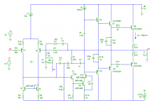
Have you ever tried TPC and TMC together*?
e.g. C1 = 1.2 nF, C2 = 68 pF, C3 = 1nF, R1 = 390R, R2 = 470R (see attached schematic)
What does your sim have to say about this?
*I guess strictly speaking this should be called TTPC (Transitional Two Pole Compensation)
Have you ever tried TPC and TMC together*?
e.g. C1 = 1.2 nF, C2 = 68 pF, C3 = 1nF, R1 = 390R, R2 = 470R (see attached schematic)
What does your sim have to say about this?
*I guess strictly speaking this should be called TTPC (Transitional Two Pole Compensation)
Attachments
Last edited:
TTPC
Hi Harry,
I've tried zillions of compensation schemes, maybe also this one, but can't remember it.
Anyhow, I will simulate your circuit and I keep you informed.
Cheers,
E.
Hi Harry,
I've tried zillions of compensation schemes, maybe also this one, but can't remember it.
Anyhow, I will simulate your circuit and I keep you informed.
Cheers,
E.
Edmond,
Have you ever tried TPC and TMC together*?
e.g. C1 = 1.2 nF, C2 = 68 pF, C3 = 1nF, R1 = 390R, R2 = 470R (see attached schematic)
What does your sim have to say about this?
*I guess strictly speaking this should be called TTPC (Transitional Two Pole Compensation)
Andy_c tried this here:
http://www.diyaudio.com/forums/soli...terview-negative-feedback-51.html#post1160190
It was found to be unstable here:
http://www.diyaudio.com/forums/soli...terview-negative-feedback-56.html#post1160936
and here:
http://www.diyaudio.com/forums/solid-state/94676-bob-cordell-interview-negative-feedback-57.html
Last edited:
TTPC
Hi Harry,
I fully understand the rationale behind your idea, but regrettably, the results are a bit disappointing.
TTPC THD20=32ppm
TPC THD20=25ppm (R2=inf)
TMC THD20=19ppm (R1=inf)
Actually, I'm not that surprised, as in the past I got comparable results from similar circuits.
BTW1, to save time (and because I'm lazy) I've used a slightly different amp circuit, as this one happened to be at hand (see below). I hope you don't mind.
BTW2, to extend the loop gain at the high end of the audio spectrum, you might try ETMC, see http://www.diyaudio.com/forums/soli...erview-negative-feedback-301.html#post2352970 and further.
Cheers,
E.
Attachments
Hi Edmond, thanks for checking it out.
This is quite odd. Any thoughts on what's going on here? Did you try with C1 and C2 reversed as you found in the normal TPC case this was oddly slightly better from a THD perspective.
You won't have seen it, but Mike linked back to earlier in the thread where andy_c pondered TTPC, although I didn't see any results of simulations or testing.
No problem, this is exactly what I was expecting you to do.
Thanks again,
Harry.
I fully understand the rationale behind your idea, but regrettably, the results are a bit disappointing.
TTPC THD20=32ppm
TPC THD20=25ppm (R2=inf)
TMC THD20=19ppm (R1=inf)
This is quite odd. Any thoughts on what's going on here? Did you try with C1 and C2 reversed as you found in the normal TPC case this was oddly slightly better from a THD perspective.
Actually, I'm not that surprised, as in the past I got comparable results from similar circuits.
You won't have seen it, but Mike linked back to earlier in the thread where andy_c pondered TTPC, although I didn't see any results of simulations or testing.
BTW1, to save time (and because I'm lazy) I've used a slightly different amp circuit, as this one happened to be at hand (see below). I hope you don't mind.
No problem, this is exactly what I was expecting you to do.
Thanks again,
Harry.
Stability
Briefly returning to stability issues, here are a few things I believe. Some of these concepts are covered in my book in Chapter 4.
First, we generally think of the simple Miller-compensated amplifier as having an ideal 6 dB/octave rolloff with 90 degrees of phase margin. As we add excess phase from unwanted poles and delay, the phase margin will become less than 90 degrees. Indeed, without added zeros somewhere, we can never in practice really have 90 degrees of phase margin with such an amplifier.
Moreover, we usually like to have the open loop gain curve go through the gain crossover point (Fc) at a rate of about 6 dB/octave. In fact, I believe that the open-loop gain one octave below Fc should never be greater than +7 dB, and the OLG one octave above Fc should never be below -7 dB. Even with TPC amplifiers and ones that have zeros, this constraint should always be satisfied, in my opinion.
For most amplifiers that satisfy this criteria, overshoot and gain peaking can be a reasonable indicator of phase margin and stability IF there is adequate gain margin (although TPC designs will exhibit some overshoot anyway). I discuss this in my book in Chapter 4, and Figure 4.10 shows an approximate relationship between peaking, overshoot, and phase margin. That graph is from simulation of an amplifier where four excess poles are moved in from a high frequency, degrading the phase margin, introducing peaking and overshoot. The resulting peaking and overshoot are then plotted against the phase margin.
In my view, phase margin should never be less than 45 degrees under all anticipated operating and load conditions. This goes for no-load, 8-ohm load, 4-ohm load and foreseeable reactive load conditions. It is also desirable that the phase margin not be substantially degraded when the amplifier is operating away from its small-signal quiescent point, such as when it is delivering high current or the output is near the rails.
Just as importantly, and sometimes overlooked, gain margin should never be less than 6 dB. If the amplifier approximately satisfies the above criteria for a 6-dB/octave slope through and about Fc, this approximately translates to saying that the amplifier can still be stable if the gain crossover frequency is doubled. For example, one might lighten the compensation by a frequency factor of two, or one might reduce the closed-loop gain by a factor of 2.
The square wave response of an amplifier with inadequate gain margin can sometimes fool one into thinking the amplifier is safely stable.
Finally, the introduction of zeros, either in the forward path or the feedback path, always must be done with great care, as it can compromise gain margin.
Cheers,
Bob
It is also desirable that the phase margin not be substantially degraded when the amplifier is operating away from its small-signal quiescent point, such as when it is delivering high current or the output is near the rails.
Cheers,
Bob
How would you simulate that ?? Incease the small signal AC analysis source up to a very high level ?? 😕
OS
- Home
- Amplifiers
- Solid State
- Bob Cordell Interview: Negative Feedback