How would you simulate that ?? Incease the small signal AC analysis source up to a very high level ?? 😕
OS
Hello OS
Put a DC voltage on the input that forces the output to one or the other supply rail.
Maybe Bob has another way of doing it.
Regards
Arthur
Add a dc offset voltage?How would you simulate that ?? Incease the small signal AC analysis source up to a very high level ?? 😕
OS
For current, connect a current source to the output?
Hi Dimitri,
It really is hard to comment on that without specific information. But what Pete (aka OS) described might fall in the same category as syn08 has experienced with the PGP amp. See: http://www.diyaudio.com/forums/soli...erview-negative-feedback-314.html#post2369013
Best regards,
Edmond.
This was with the LTP/VAS degeneration tailored to a 47pF silver mica or 100/ 220p TMC. I simply turned off the amp , swapped caps , retried. Conversely , going over 100pF with this amp will make the sound "muddy". I just happen to have 50 - 47pF's and it is easy to design the rest of the amp around them with proper degeneration of R11/12 -14/15 (below). Any comparisons would be subjective as it is my ears making the evaluation, but there is an audible difference .. for sure. Sourcing / $$$ is yet another design criteria for me.
With the unity gain point dropped back down to 700k-800k, a 33-39p could be made to sound identical to the 47p. 🙂
Below 2 is the bode that I know will allow me to prototype without misfortune.
OS
Attachments
Add a dc offset voltage?
For current, connect a current source to the output?
I tried that with a hefty DC offset on the AC sweep and lost 10dg. margin. I also plotted my bode with different capacitive loads and saw the effect on phase. None would turn the amp into a oscillator and the UG point stayed rock solid at 775khz.
OS
Last edited:
Hello OS
Put a DC voltage on the input that forces the output to one or the other supply rail.
Maybe Bob has another way of doing it.
Regards
Arthur
Hi Arthur,
Yes, this is basically what can be done in simulation. We would apply a DC input to a DC-coupled version of the amplifier, pushing it close to the rail, while running an AC sim on it or a small-signal square wave transient simulation. Note also that the output current, even at 0V output, can be forced by an external current source connected to the output.
Cheers,
Bob
How would you simulate that ?? Incease the small signal AC analysis source up to a very high level ?? 😕
OS
unfortunately no - Spice .AC doesn't actually run a simulation - it just does the DC operating point analysis and then linearizes the network components about that bias point - AC signal level has absolutely no effect on the shape of the curves - only on the scale factor
I have occasionally tried to point out the utility of having a Save/Restore State functionality that would allow you to reach a dynamic operating point (with I thru C, V across L) in a .TRAN sim that could then be used in the .AC analysis
I find really high loop gain circuits become fragile in the DC operating point calculation - some have large transients on startup - others simply never find a DC operating point - some I have dissected to lower gain local loops with SW elements and then after start up reconfigured to the high gain configuration - after which the circuits sim fine - so the problem is definitely in the DC op point calcs
the ability run a “local” .AC to deal with full reactive load operating points would allow looking a stability with slewing
maybe if others can appreciate the potential utility and request the feature?
Last edited:
unfortunately no - Spice .AC doesn't actually run a simulation - it just does the DC operating point analysis and then linearizes the network components about that bias point - AC signal level has absolutely no effect on the shape of the curves - only on the scale factor
I have occasionally tried to point out the utility of having a Save/Restore State functionality that would allow you to reach a dynamic operating point (with I thru C, V across L) in a .TRAN sim that could then be used in the .AC analysis
I find really high loop gain circuits become fragile in the DC operating point calculation - some have large transients on startup - others simply never find a DC operating point - some I have dissected to lower gain local loops with SW elements and then after start up reconfigured to the high gain configuration - after which the circuits sim fine - so the problem is definitely in the DC op point calcs
the ability run a “local” .AC to deal with full reactive load operating points would allow looking a stability with slewing
maybe if others can appreciate the potential utility and request the feature?
I do ,too.(sometimes "fragile" DC OP issues) The easier it is for the simulator to find that point (with a direct newton reiteration) the better the circuit. Some prospective circuits need to go to a stepping mode to find the DC operating point. How this plays out in the real amps is interesting , the direct newton amp is VERY tolerant of component changes and degenerations while the one that made the simulator "sweat" is quite picky both in simulation and in the real world. A "trick" Keentoken showed me is to fix the differential's DC points with a simulated battery bypassing the DC blocking cap and input cap.
OS
Finally, the introduction of zeros, either in the forward path or the feedback path, always must be done with great care, as it can compromise gain margin.
True.
overshoot
Some people regard overshoot as acceptable. And I agree that, provided the stability is not at stake, you can't hear it. So all my whining about the phase dip and companion overshoot created by TPC looks rather pointless, not to say mad. But in the light of striving for an ultra flat frequency response, ultra low distortion and ultra low phase dispersion (things you also can't hear) I wonder how mad is mad? Is the quest for a flat step response madder than the quest for a flat frequency response?
Just my two cents.
Cheers,
E.
Good questions. I don't think any of this is mad or pointless. My take was that by allowing *some* overshoot, you could have a bit more hf feedback and lower distortion. Is it worthwhile? Is it audible? Probably not.
But it is/was an interesting discussion.
jan didden
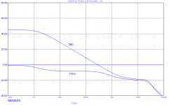
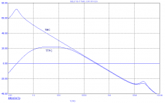
TTPC
You're welcome.
Hi Harry,
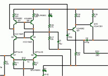
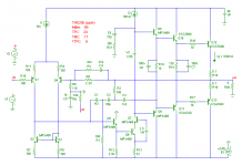
Actually, it is not that odd at all. The point is that TMC is only effective if the VAS has sufficient gain, a necessary condition that is easily overlooked. Adding C1 and R1 kills the local loop gain around the VAS and OPS, see the 1st picture.
We can increase the gain by unloading the VAS output, simply by connecting C3 to the emitter of the pre-driver. As you already remarked, this is not without danger, so I tamed the HF loop gain by means of a light shunt compensation network, see 2nd picture, C8 & R21.
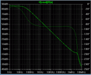
Now the circuit works as expected: the loop gain isn't spoiled any longer (see 3rd pic) and THD20 drops to 9ppm, an improvement of about 6dB. Notice that no effort has been undertaken to optimize the component values. So, probably this figure can be further improved.
I suppose you are much happier now.
Cheers,
E.
Hi Edmond, thanks for checking it out.
You're welcome.
This is quite odd. Any thoughts on what's going on here? Did you try with C1 and C2 reversed as you found in the normal TPC case this was oddly slightly better from a THD perspective.
[snip]
Thanks again,
Harry.
Hi Harry,
Actually, it is not that odd at all. The point is that TMC is only effective if the VAS has sufficient gain, a necessary condition that is easily overlooked. Adding C1 and R1 kills the local loop gain around the VAS and OPS, see the 1st picture.
We can increase the gain by unloading the VAS output, simply by connecting C3 to the emitter of the pre-driver. As you already remarked, this is not without danger, so I tamed the HF loop gain by means of a light shunt compensation network, see 2nd picture, C8 & R21.
Now the circuit works as expected: the loop gain isn't spoiled any longer (see 3rd pic) and THD20 drops to 9ppm, an improvement of about 6dB. Notice that no effort has been undertaken to optimize the component values. So, probably this figure can be further improved.
I suppose you are much happier now.
Cheers,
E.
Attachments
You're welcome.
Hi Harry,
Actually, it is not that odd at all. The point is that TMC is only effective if the VAS has sufficient gain, a necessary condition that is easily overlooked. Adding C1 and R1 kills the local loop gain around the VAS and OPS, see the 1st picture.
We can increase the gain by unloading the VAS output, simply by connecting C3 to the emitter of the pre-driver. As you already remarked, this is not without danger, so I tamed the HF loop gain by means of a light shunt compensation network, see 2nd picture, C8 & R21.
Now the circuit works as expected: the loop gain isn't spoiled any longer (see 3rd pic) and THD20 drops to 9ppm, an improvement of about 6dB. Notice that no effort has been undertaken to optimize the component values. So, probably this figure can be further improved.
I suppose you are much happier now.
Cheers,
E.
Hi Edmond,
I have also seen that taking the compensation feedback from the pre-driver is dangerous to the stability of the compensation loop, and have also noted the need for the light shunt compensation at the collector of the VAS. This shunt compensation makes the VAS act a bit more like it does when the Miller feedback is taken from the VAS, with the Miller capacitor providing some loading and controlling the gain bandwidth of the compensation loop. Taking the compensation from the pre-driver unloads the VAS, but sometimes by too much.
Taking the compensation feedback from the pre-driver can be especially dangerous when the VAS is a Darlinton-cascode, as the VAS self-loading is less and there are more transistors in the compensation loop, adding excess phase.
Cheers,
Bob
Good questions. I don't think any of this is mad or pointless. My take was that by allowing *some* overshoot, you could have a bit more hf feedback and lower distortion. Is it worthwhile? Is it audible? Probably not.
But it is/was an interesting discussion.
jan didden
Hi Jan,
As a matter of fact, I also accept some overshoot. However, what kind of overshoot we are talking about anyhow? Small signal, large signal, under best case conditions, or under worst case condition, simulated or in real life?
My policy is that under simulated best case conditions, there should be no overshoot and the phase margin of all loops should be close to 90 degrees (not always possible, in particular with regard to the local Miller loop). This approach leaves plenty of room for 'setbacks':
First, we all know that the results of a sim are flattered most of the time, because of inaccurate models, parasitics not accounted for, component tolerance, aging, etc.
Second, when the output approaches the supply rail voltage (large signal conditions) Cgd or Cob of the drivers and output devices are much, much larger.
All these factors will have a significant effect on the stability and/or overshoot.
So I don't think that striving for no overshoot under flattered and best case condition is an unnecessary strict design rule. Better safe than sorry.
Cheers,
E.
PS: Most of my designs suffer from some large signal overshoot. This seems to be unavoidable in high feedback systems.
Finally, the introduction of zeros, either in the forward path or the feedback path, always must be done with great care, as it can compromise gain margin.
Strictly true only if you already had only a single pole roll-off to begin with, or if the roll-off is peaky in the region of unity gain frequency.
Last edited:
Hi Edmond,
I have also seen that taking the compensation feedback from the pre-driver is dangerous to the stability of the compensation loop, and have also noted the need for the light shunt compensation at the collector of the VAS. This shunt compensation makes the VAS act a bit more like it does when the Miller feedback is taken from the VAS, with the Miller capacitor providing some loading and controlling the gain bandwidth of the compensation loop. Taking the compensation from the pre-driver unloads the VAS, but sometimes by too much.
Taking the compensation feedback from the pre-driver can be especially dangerous when the VAS is a Darlinton-cascode, as the VAS self-loading is less and there are more transistors in the compensation loop, adding excess phase.
Cheers,
Bob
see:
http://www.diyaudio.com/forums/soli...erview-negative-feedback-313.html#post2368303
We can increase the gain by unloading the VAS output, simply by connecting C3 to the emitter of the pre-driver. As you already remarked, this is not without danger, so I tamed the HF loop gain by means of a light shunt compensation network, see 2nd picture, C8 & R21.
Unfortunately the ''VAS'' (TIS) output is now loaded by the shunt network negating the purpose of connecting C3 to the predriver.
Better then to stick to connecting minor loop compensation networks to the output of the TIS.
Unfortunately the ''VAS'' (TIS) output is now loaded by the shunt network negating the purpose of connecting C3 to the predriver.
Better then to stick to connecting minor loop compensation networks to the output of the TIS.
Yes, but that 'light shunt' comes into play at higher frequencies than if you would connect the network to the Vas output instead of the predriver output. Seems to me that there is a 'net gain' of loop gain in the higher freq region.
jan didden
True. But I reckon you need the relatively low output impedance (due to the shunt feedback) of a compensation network loaded TIS to properly drive the output stage.
- Home
- Amplifiers
- Solid State
- Bob Cordell Interview: Negative Feedback