Hi Ostripper
if I understood right
in my symasym
I should add ~470p cap to existing 100p cap in series and connect a resistor from the middle of the caps to negative rail
what should be resistor's value?
The original sym is a totally different amp , it would not break out in oscillation but you would lose the "flavor" of the original compensation. Mike B's original uses a dominant pole shunt compensation on the front side (driver side) and a"dummy' 100pF on the "backside" to equally load the input stage. Mike B's also uses high Cob 2nXXXX VAS devices ... totally different.
TMC is NOT TPC with the R going to Vee (V-). It is a nested feedback loop from the output directly feeding into the VAS's miller loop.
OS
Also I would like to add here something that I didn't really emphasise in the paper: the optimum ratio of the capacitor sizes is exactly the reverse of that suggested by D. Self and R. Slone in their books, i.e. it's the capacitor that connects to the input stage that should be the large one, not the one that connects to the VAS collector.
Also not mentioned in the paper is that of course the loop gain phase margin can be further manipulated with lead compensation in the global feedback network (i.e. by adding an RC series network in parallel with feedback resistor).
This was covered in a paper i wrote over four years ago as jan can confirm.
This was covered in a paper i wrote over four years ago as jan can confirm.
link? Title of paper? Anything?
p.s. Sorry for spelling your name wrong before; time window for editing post had closed by the time I noticed.
Last edited:
This was covered in a paper i wrote over four years ago as jan can confirm.
... and which I think should be published 😉
jan
[snip]
Hi micheal. Did you simulate this? If so, how? If the minor loop is unstable, it doesn't seem to have any consequences in the amplifiers that I have built.
Michael excels in making unsubstantiated comments.
Also I would like to add here something that I didn't really emphasise in the paper: the optimum ratio of the capacitor sizes is exactly the reverse of that suggested by D. Self and R. Slone in their books, i.e. it's the capacitor that connects to the input stage that should be the large one, not the one that connects to the VAS collector. Note that somewhat counter-intuitively, all other things being equal, increasing the resistor value will increase the current requirement from the input stage (of course it will also change the frequency of the zero in the loop-gain function).
Hi Harry,
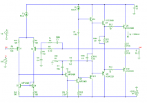
Indeed, your choice of capacitor values is somewhat counter-intuitive. So I've run some sims using a fairly standard amp topology. The only thing that's a little less 'standard' is the compensation take-off point, which is moved to the output of the pre-driver. In this way the VAS output isn't (unnecessary) loaded by the compensation stuff.
Here are some results (C3=0):
Code:
C1 (pf)   C2 (pF)   R1 (Ohm)  THD20 (ppm)   PM (deg)  ULGF (MHz)  Remarks
1200      68        1T        104            82         1         Miller
1200      68        390        28            65         1         TPC
68       1200       390        24            65         1         TPC
Clearly, distortion figures have improved WRT to ordinary Miller compensation, though at the expense of the phase margin (PM). Also your 'counter-intuitive' capacitor values doesn't seem the best choice, at least in this case. Probably, other factors are involved that blur your theoretical results.

Also not mentioned in the paper is that of course the loop gain phase margin can be further manipulated with lead compensation in the global feedback network (i.e. by adding an RC series network in parallel with feedback resistor).
In an attempt to improve the step response, I've added some lead compensation by means of C3=390pF and R2=1k. Now the overshoot has gone. The phase margin is slightly improved (66 degrees), but the unity loop gain frequency (ULGF) increased fom 1 to 2.9MHz!
This is really what we call "putting the cart before the horse"*. If -for stability reasons- we put the ULGF back to 1MHz by tripling all capacitor values, all what we have gained by TPC (in terms of THD) is almost lost by this lead compensation. Clearly compensating two pole compensation is not the way to go.
There are other ways to remove (read: mask) to overshoot, for example a low pass filter in front of the input. However, this (fraudulent!) trick belongs to the same category as putting a brick wall filter (fc=21kHz) behind the output and then claiming that THD20k is zero!

BTW, if you don't mind, I've also simmed the TMC variant (by connecting the left side of R1 to the output):
Code:
C1 (pf)   C2 (pF)   R1 (Ohm)  THD20 (ppm)   PM (deg)  ULGF (MHz)  Remarks
1200      68        390       2200           99        0.06       TMC bad!
68       1200       390        18            82         1         TMC
As expected, the 1st combination of caps is disastrous, though the 2nd combination is clearly the winner, in every respect: THD, PM as well as step response.
Cheers,
E.
* /OT In Dutch we say "het paard achter de wagen spannen", which means: putting the horse behind the cart. Ain't that funny?
Attachments
does that mean that relocating R1 from ground to output changes two pole compensation (TPC) to TMC?
BTW,
a nice report on comparing the different setups.
BTW,
a nice report on comparing the different setups.
Indeed, your choice of capacitor values is somewhat counter-intuitive. So I've run some sims using a fairly standard amp topology. The only thing that's a little less 'standard' is the compensation take-off point, which is moved to the output of the pre-driver. In this way the VAS output isn't (unnecessary) loaded by the compensation stuff.
I tried that once in a real amplifier and it didn't work all that well (VHF oscillations, not sure if it was a local feedback loop stability issue or a "parasitic" oscillation problem; didn't really have time to explore it in detail)
In the audio band, the current required to drive C2 increases significantly if it is the larger one; in either case the current required to drive C1 in the audio band is much smaller than the current required to drive a single-pole compensation miller capacitor. If you sim with the compensation take-off point in the VAS collector, I think you should see a THD improvement when C1 is large, but maybe not as you have a triple output stage. BTW, what simulator do you use? The one I have seems to give highly dubious distortion numbers.
In an attempt to improve the step response, I've added some lead compensation by means of C3=390pF and R2=1k. Now the overshoot has gone. The phase margin is slightly improved (66 degrees), but the unity loop gain frequency (ULGF) increased fom 1 to 2.9MHz!
If you experiment further with the lead compensation values, you should find that it's possible to change the phase margin without altering the ULGF.
Last edited:
That's right.does that mean that relocating R1 from ground to output changes two pole compensation (TPC) to TMC?
Thx!BTW,
a nice report on comparing the different setups.
Cheers,
E.
I tried that once in a real amplifier and it didn't work all that well (VHF oscillations, not sure if it was a local feedback loop stability issue or a "parasitic" oscillation problem; didn't really have time to explore it in detail)
Hi Harry,
The devil is in the detail. Sometimes it works, other times it oscillates. Nevertheless, I choose this take-off point to demonstrate the specific properties of TPC (and TMC) itself, without blurring the results by (potential) loading effect on the VAS output.
As a matter of fact, I've also simmed this amp with the compensation cap directly tied to the VAS output and the result were near identical.
In the audio band, the current required to drive C2 increases significantly if it is the larger one; in either case the current required to drive C1 in the audio band is much smaller than the current required to drive a single-pole compensation miller capacitor. If you sim with the compensation take-off point in the VAS collector, I think you should see a THD improvement when C1 is large.
I agree with your reasoning, but regrettably I didn't see an improvement.
If C1=1n2 & C2=68p: THD20=29ppm
If C1=68p & C2=1n2: THD20=20ppm
Why?! Maybe another distortion mechanism spoils it. Perhaps because the input stage has to put out more current, hence more distortion???
BTW, what simulator do you use? The one I have seems to give highly dubious distortion numbers.
I'm using MicroCap V9, and which simulator do you use?
If you experiment further with the lead compensation values, you should find that it's possible to change the phase margin without altering the ULGF.
Sorry, I don't see how to do that. Could you give us an example, please?
Cheers,
E.
I'm using MicroCap V9, and which simulator do you use?
ISIS (part of Proteus form LabCenter Electronics)
Sorry, I don't see how to do that. Could you give us an example, please?
In a different amplifier from the one in the paper, I had 820R and 6p8 lead components (with a 10k feedback resistor). This lead to a minimal change in ULGF but about 24 degree improvement in phase margin.
Hi Harry,
Okay. Using a 2k2 FB resistor, this is equivalent to 180R and 31pF.
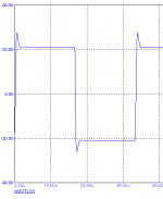
Indeed, the phase margin improves from 64 to 90 degrees with an increase in ULGF of (only) 15%. However, I was more concerned about the overshoot of the step response. Admittedly, the PM is much better now, though the overshoot is still there (see pic).
In the past I also complained about this 'feature' of TPC. By then, Micheal objected that this could easily be repaired by means of only one C and one R. I suppose it was just lead compensation, what else? So for a critically damped step response we need a much larger lead compensation cap (390pF), with all its evil consequences. This was what I meant with: "putting the cart before the horse".
Cheers,
E.
Okay. Using a 2k2 FB resistor, this is equivalent to 180R and 31pF.
Indeed, the phase margin improves from 64 to 90 degrees with an increase in ULGF of (only) 15%. However, I was more concerned about the overshoot of the step response. Admittedly, the PM is much better now, though the overshoot is still there (see pic).
In the past I also complained about this 'feature' of TPC. By then, Micheal objected that this could easily be repaired by means of only one C and one R. I suppose it was just lead compensation, what else? So for a critically damped step response we need a much larger lead compensation cap (390pF), with all its evil consequences. This was what I meant with: "putting the cart before the horse".
Cheers,
E.
Attachments
180R and 31pF
Hi Edmond, I'm afraid this will increase susceptibility to RFI substantially. Can you feed this network from other node, e.g. driver output?
better PSRR
Hi Pete,
Not always, as it depends on the actual implementation of ETMC. As you know, the improvement in PSRR was just a by product, a spin-off, from ETMC. C2 in this page: http://www.diyaudio.com/forums/soli...erview-negative-feedback-301.html#post2352970 contributes to a better PSSR.
But here you see another implementation: http://www.diyaudio.com/forums/soli...erview-negative-feedback-304.html#post2357325
In this case however, the ETMC stuff don't improve the PSRR. Therefore I added C2 and R9, which do the trick. You can use this technique with any amp (with or without TMC, ETMC, or whatever) as long as there is a current mirror to which you can tie the RC network.
Notice that C2=C7. The optimal value for R9 is easiest found by trial-and-error.
Cheers,
E.
PS: To avoid possible confusion, you better use my first name, as there is one more person (SY) who listens to the name 'Stuart'. 😉
[snip]
Stuart , I have room on my next proto board for some passives , will ETMC really buy me better PSRR ?? That seems to be the only subtle improvement that can be achieved with this design. THD is licked !! 🙂
[snip]
OS
Hi Pete,
Not always, as it depends on the actual implementation of ETMC. As you know, the improvement in PSRR was just a by product, a spin-off, from ETMC. C2 in this page: http://www.diyaudio.com/forums/soli...erview-negative-feedback-301.html#post2352970 contributes to a better PSSR.
But here you see another implementation: http://www.diyaudio.com/forums/soli...erview-negative-feedback-304.html#post2357325
In this case however, the ETMC stuff don't improve the PSRR. Therefore I added C2 and R9, which do the trick. You can use this technique with any amp (with or without TMC, ETMC, or whatever) as long as there is a current mirror to which you can tie the RC network.
Notice that C2=C7. The optimal value for R9 is easiest found by trial-and-error.
Cheers,
E.
PS: To avoid possible confusion, you better use my first name, as there is one more person (SY) who listens to the name 'Stuart'. 😉
In my reading of control theory I don't see justification for your insistence on flat step response - control loops are often designed with 30-60 degree phase margin and up to 2x overshoot isn't per se indicative of bad design - a pre-filter is an acceptable part of the system response design when optimizing working frequency desensitivity leads to a overshoot in the feedback loop
search Bode's Maximum Feedback, "2 degree of freedom" feedback system (Horowitz)
while 1/2 a centruy old these concepts are treated in contemporary control theory books, papers by Goodman, Lurie, Mitchell...
search Bode's Maximum Feedback, "2 degree of freedom" feedback system (Horowitz)
while 1/2 a centruy old these concepts are treated in contemporary control theory books, papers by Goodman, Lurie, Mitchell...
Last edited:
1. Control theory or not, why not simply use a compensation technique that doesn't cause overshoot at all? Just avoid it avoid it instead of cure it.
2. As for audio applications and highly reactive loads, 30 degrees PM is totally unacceptable.
2. As for audio applications and highly reactive loads, 30 degrees PM is totally unacceptable.
I think Bode's integral relations show that for the same underlying "plant" you have higher loop gain at the "working frequency" if you accept some overshoot in the compensation at the unity loop gain intercept
PM obviously should be measured with worst case anticipated load - or do you also insist on testing without a load isolation network too?
I suspect the flat overshoot response is common in audio amps because it can be done, it may in simple enough amps indicate a large stability margin for those not using more sophisticated evaluation of stability and designers don't perceive a large performance cost - but has it really been critically examined? - to the extent of your making it a optimization goal in itself?
Last edited:
Hi Edmond, I'm afraid this will increase susceptibility to RFI substantially.
Not an issue with a correctly designed load isolation network.
Right! One more reason to not use TPC. 😀
Cheers,
E.
Nope! What are the 'other reasons'?
- Home
- Amplifiers
- Solid State
- Bob Cordell Interview: Negative Feedback