Amps
Hello Glen,
May I ask why with a JFET input why you need a 2uF input coupling cap.
Can I ask what the PSRR is for the negative and positive powersupplies respectively at 20KHz , without using regulators.
Regards.
Arthur
Hello Glen,
May I ask why with a JFET input why you need a 2uF input coupling cap.
Can I ask what the PSRR is for the negative and positive powersupplies respectively at 20KHz , without using regulators.
Regards.
Arthur
Re: Amps
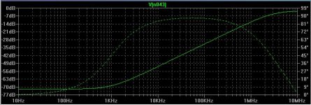
PSR plot attached below (soild line). The coupling cap is there to block DC from the source. It incurrs a high pass pole of 0.6Hz.
I did make a boo boo in the schematic though. The mute relay needs to be wired after the 2.2uF coupling cap to prevent audible clicks when it operates due to any DC from the source.
I will ammend the drawing when I get time.
PHEONIX said:Hello Glen,
May I ask why with a JFET input why you need a 2uF input coupling cap.
Can I ask what the PSRR is for the negative and positive powersupplies respectively at 20KHz , without using regulators.
Regards.
Arthur
PSR plot attached below (soild line). The coupling cap is there to block DC from the source. It incurrs a high pass pole of 0.6Hz.
I did make a boo boo in the schematic though. The mute relay needs to be wired after the 2.2uF coupling cap to prevent audible clicks when it operates due to any DC from the source.
I will ammend the drawing when I get time.
Attachments
Re: Re: Amps
Do you think a simulated 40 and something dB PSRR @20KHz is good enough?
Could you check if both PSRR- and PSRR+ are identical?
G.Kleinschmidt said:
PSR plot attached below (soild line). The coupling cap is there to block DC from the source. It incurrs a high pass pole of 0.6Hz.
I did make a boo boo in the schematic though. The mute relay needs to be wired after the 2.2uF coupling cap to prevent audible clicks when it operates due to any DC from the source.
I will ammend the drawing when I get time.
Do you think a simulated 40 and something dB PSRR @20KHz is good enough?
Could you check if both PSRR- and PSRR+ are identical?
Re: Re: Amps
Hi Glen
Is the PSRR the same for both positive and negative supplies. This graph is it for pos or neg supply.
Regards
Arthur
G.Kleinschmidt said:
PSR plot attached below (soild line). The coupling cap is there to block DC from the source. It incurrs a high pass pole of 0.6Hz.
I did make a boo boo in the schematic though. The mute relay needs to be wired after the 2.2uF coupling cap to prevent audible clicks when it operates due to any DC from the source.
I will ammend the drawing when I get time.
Hi Glen
Is the PSRR the same for both positive and negative supplies. This graph is it for pos or neg supply.
Regards
Arthur
Re: Re: Re: Amps
Yes, it's the same.
Cheers,
Glen
PHEONIX said:
Hi Glen
Is the PSRR the same for both positive and negative supplies. This graph is it for pos or neg supply.
Regards
Arthur
Yes, it's the same.
Cheers,
Glen
Re: Re: Re: Amps
Yes, I think that is good enough. Read what D.Self says about this and supply rail decoupling to the VAS. With regulated rails it's a complete non issue.
Cheers,
Glen
syn08 said:
Do you think a simulated 40 and something dB PSRR @20KHz is good enough?
Could you check if both PSRR- and PSRR+ are identical?
Yes, I think that is good enough. Read what D.Self says about this and supply rail decoupling to the VAS. With regulated rails it's a complete non issue.
Cheers,
Glen
Re: Re: Re: Re: Amps
Figure out, I've read what D. Self says about. Have you checked both PSRR+ and PSRR-? Obviously, regulating the rails would help.
G.Kleinschmidt said:
Yes, I think that is good enough. Read what D.Self says about this and supply rail decoupling to the VAS. With regulated rails it's a complete non issue.
Cheers,
Glen
Figure out, I've read what D. Self says about. Have you checked both PSRR+ and PSRR-? Obviously, regulating the rails would help.
Re: Re: Re: Re: Re: Amps
Yes, both rails measure the same as I've said already. I know that you didn't actually design most of it, but are you actually aware of your PGP's front end PSR?
syn08 said:
Figure out, I've read what D. Self says about. Have you checked both PSRR+ and PSRR-? Obviously, regulating the rails would help.
Yes, both rails measure the same as I've said already. I know that you didn't actually design most of it, but are you actually aware of your PGP's front end PSR?
Re: Re: Re: Re: Re: Re: Amps
Yes I am, thanks for asking.
G.Kleinschmidt said:
Yes, both rails measure the same as I've said already. I know that you didn't actually design most of it, but are you actually aware of your PGP's front end PSR?
Yes I am, thanks for asking.
Re: Re: Re: Re: Re: Re: Re: Amps
You're welcome.
syn08 said:
Yes I am, thanks for asking.
You're welcome.
syn08 said:
Bob,
I took this opportunity and measured the PGP amp behaviour; no doubts, the PGP amp qualifies as "high feedback" 🙂
The 19KHz signal was generated by a PM5193 function generator, while the 20KHz signal was generated by the HP3562A analyzer. Both signals were 2.600 Vpeak-peak into 50ohm, the PGP gain is measured 28.94dB. Therefore, the output reference (0dB level) was 12.87Veff.
Pretty difficult task mainly because, as also mentioned on the PGP web site, the spectral purity of both test signals and the instruments output stages linearity is pretty poor, resulting in numerous artifacts. Mixing the signals in a AD797, LT1115 or LM4562 did help, but substracting the opamp distortion and noise contributions was very difficult so I gave up this path... Using the Amber 5500 signal (very low distortion) was not an option as well - the 50ohm output stage (I have the high output level option) has a very poor linearity.
Finally, direct dual channel (amp input/amp output) measurements and carefully calibrating the channels gains allows (after normalizing the signals) substracting the spectra and extracting the PGP amp contribution. Averaging was set to 1024 and triggering was always set on the amp input signal.
Here are the results:
F[KHz] Level [dB]
----------------------------------
13 -111.50
14 -105.02
15 -106.23
16 -104.81
17 -110.98
18 -111.42
Unfortunately, the HP3562A spectrum analyzer is limited to 100KHz BW with a frequency span of maximum 50KHz , so I canot measure independently the 19/20KHz single tone 5th harmonic and up. Because of this limitation, I have to admit I am not sure how to interpret the measured absolute values and to correlate them with other measurements. In particular I am not sure how to quatitatively correlate the 18KHz component with the 3rd harmonic single tone measurements (the single tone 20KHz 3rd harmonic measures under -120dB) but looking at the relative values they seem to confirm the hypothesis of creation of new, higher-order distortion products, or increasing those already present. The highest component seems to be related to the 7th harmonic.
I have a PM5193. But don't know how to set the duty cycle. Could you help me ? Thanks very much.
liu0ju@hotmail.com
liu0 said:
I have a PM5193. But don't know how to set the duty cycle. Could you help me ? Thanks very much.
liu0ju@hotmail.com
I don't think it's possible.
Where complementary symmetry and traditional miller compensation rules supreme.
Hi Ho
I’m now in the final design/construction stages of my K800AB amplifier.
Since my last postings detailing the full complementary / symmetry front-end design that is capable of slewing ~300V/us and ~600V/us when miller compensated for unity loop gain frequencies of 1MHz and 2MHz respectively, I have made a few revisions.
These stemmed from the difficulty in driving the massive output stage.
The output stage consists of twenty pairs of MJL3281/MJL1302 power transistors divided into five groups of four parallel-connected pairs. Each group of four pairs has its own MJE15032/MJE15033 complementary driver pair, and these five pairs of drivers are driven from a single MJE15030/MJE15031 complementary pair.
The difficulty arises from the fact that the MJE15030/MJE15031 pre-driver pair presents a significant capacitive load. This is especially so when driven at a high slew rate, causing high transient emitter currents to flow.
Driving such a stage directly from the VAS in its previous incarnation would result in a mediocre slew rate at best.
The design required extensive buffering of the VAS from the triple emitter follower output stage in order to achieve a high slew rate. While perfectly doable, this is an inelegant PITA to implement, especially so when it comes to temperature compensating the output stage.
Driving a capacitive load at very high slew rates directly from the VAS collector also causes issues WRT to frequency compensation. Previous experiments to achieve adequate performance with feed-forward compensation were the “miller” compensation capacitor is returned from the VAS collector to the inverting input were less than promising.
The problem was that the “miller” feedback capacitor at ~30pF or so was not the dominant capacitive load on the VAS. Driving a relatively high capacitive load directly from the VAS collector made it difficult to compensate the miller loop (now consisting of the VAS and input long tail pairs combined) for adequate step response free of ringing and ripple.
Then I read this revealing National Semiconductor design brief:
http://www.national.com/appbriefs/files/AppBrief108.pdf
Basically, an properly built amplifier frequency compensated solely with the traditional collector-base miller compensation capacitor will be inherently immune to capacitive loading of the VAS collector, with a perfect, ringing free step response and whistle clean slew rate limiting guaranteed.
National Semiconductor took advantage of this fact in the design of an unlimited load capacitance opamp, by omitting the output stage and driving the output directly from the VAS collector.
So, I went back to the traditional collector-base miller compensation and beefed up my VAS.
A screen shot of the basic simulation is attached below. In order to achieve a high slew rate into the MJE15030/MJE15031 pre-driver pair, the VAS was trebled up. Quiescent current is 30mA and peak current is limited to +/-110mA.
This is where full complementary circuit topologies rule over unipolar or single ended ones – the VAS can be designed to deliver well over twice its quiescent current into a hefty or difficult to drive load.
For the sole purpose of demonstrating the slewing performance and step response of the VAS, the simulation was simplified with a unity gain VCVS to act as an ideal output stage.
The front-end circuit is simulated twice, driven to an output voltage of 80Vp-p with a 200kHz squarewave. The miller compensation capacitors are selected for a unity loop gain frequency of 1MHz.
The green trace shows the output voltage of the circuit on the left, which has no additional capacitive load presented to the VAS. The red trace shows the output voltage of the same circuit repeated on the right, but whose VAS collector is loaded to ground with a 1nF capacitor.
Harbuch will have my four 800VA toroids wound in 4 to 5 weeks, soon after which, with any luck, I’ll be in a position to post up some nice squarewave oscillograms made with the dummy load boiling water in a bucket.
Cheers,
Glen
An externally hosted image should be here but it was not working when we last tested it.
Hi Glen,
The idea is very appealing and I really hope it will also work with a real output stage instead of a unity gain VCVS.
Good luck.
Cheers,
Edmond.
The idea is very appealing and I really hope it will also work with a real output stage instead of a unity gain VCVS.
Good luck.
Cheers,
Edmond.
Edmond Stuart said:Hi Glen,
The idea is very appealing and I really hope it will also work with a real output stage instead of a unity gain VCVS.
Good luck.
Cheers,
Edmond.

Here it is swinging 80V p-p at 200kHz with a very non-ideal output stage.
I have made a unity gain output stage with a 2 pole roll off and stuck that into the loop.
The first pole is at 4MHz and the second pole is at 10MHz.
I am still simulating with a massive 1000pF load on the VAS collector - which is very much an overkill WRT to the real life driver transistor condition.
To cope with this the miller compensation caps had to be raised in value to bring the unity loop gain frequency down to 820kHz. (1MHz was a little too high, producing a little overshoot).
It's totally dummy proof!
Cheers,
Glen
An externally hosted image should be here but it was not working when we last tested it.
Re: Where complementary symmetry and traditional miller compensation rules supreme.
Interesting.
Just a question... Why don't you give up those MJE15030/15031 hogs and use 2SC5171/2SA1930? To my experience, they will make a huge difference.
Holler if you need Spice models.
G.Kleinschmidt said:In order to achieve a high slew rate into the MJE15030/MJE15031 pre-driver pair, the VAS was trebled up. Quiescent current is 30mA and peak current is limited to +/-110mA.
Interesting.
Just a question... Why don't you give up those MJE15030/15031 hogs and use 2SC5171/2SA1930? To my experience, they will make a huge difference.
Holler if you need Spice models.
Re: Re: Where complementary symmetry and traditional miller compensation rules supreme.
Hmmm.... They look a little wimpy. The MJE's have four times the 100uS SOA. The Toshiba parts also suffer major fT/Hfe droop at only 0.3A - the MJE's are happy out to ~2A.
Always interested in spice models though. Post them in the Spice thread??
Cheers.
Glen
syn08 said:
Interesting.
Just a question... Why don't you give up those MJE15030/15031 hogs and use 2SC5171/2SA1930? To my experience, they will make a huge difference.
Holler if you need Spice models.
Hmmm.... They look a little wimpy. The MJE's have four times the 100uS SOA. The Toshiba parts also suffer major fT/Hfe droop at only 0.3A - the MJE's are happy out to ~2A.
Always interested in spice models though. Post them in the Spice thread??
Cheers.
Glen
Re: Where complementary symmetry and traditional miller compensation rules supreme.
Hello Glenn
You obviously have some experience with Harbuck but have you ever been supplied such a large transformer for an Audio power amp from this guy? .
You have to be careful because if certain measures are not taken they will buzz like hell very annoying.
Regards
Arthur
G.Kleinschmidt said:Hi Ho
Harbuch will have my four 800VA toroids wound in 4 to 5 weeks, soon after which, with any luck, I’ll be in a position to post up some nice squarewave oscillograms made with the dummy load boiling water in a bucket.
Cheers,
Glen
An externally hosted image should be here but it was not working when we last tested it.
Hello Glenn
You obviously have some experience with Harbuck but have you ever been supplied such a large transformer for an Audio power amp from this guy? .
You have to be careful because if certain measures are not taken they will buzz like hell very annoying.
Regards
Arthur
Re: Re: Where complementary symmetry and traditional miller compensation rules supreme.
Hi.
Buzzing like hell is a no-no
No, have not ordered from them before. Just phoned on Friday for price & lead-time. I have not emailed an official order yet. Was going to email the other night just after posting here, but then I noticed that once delivery and GST is added, their 800VA toroids cost the same as from Farnell. Still sorting out my Farnell BOM, so no orders placed yet.
Cheers,
Glen
PHEONIX said:
Hello Glenn
You obviously have some experience with Harbuck but have you ever been supplied such a large transformer for an Audio power amp from this guy? .
You have to be careful because if certain measures are not taken they will buzz like hell very annoying.
Regards
Arthur
Hi.
Buzzing like hell is a no-no
No, have not ordered from them before. Just phoned on Friday for price & lead-time. I have not emailed an official order yet. Was going to email the other night just after posting here, but then I noticed that once delivery and GST is added, their 800VA toroids cost the same as from Farnell. Still sorting out my Farnell BOM, so no orders placed yet.
Cheers,
Glen
- Home
- Amplifiers
- Solid State
- Bob Cordell Interview: Negative Feedback