Re: Class-AB Output Stage Dist vs NFB
That is very interesting Bob. I guess maybe you could say that the load provides enough local NFB to the output stage such that it's already in the region where increasing the total FB more (via global FB) only reduces distortion components. Would you agree with that statement?
Bob Cordell said:The results are really interesting, to say the least. For this kind of insidious distortion, the application of negative feedback decreases all harmonic components consistently and monotonically as feedback is applied and increased.
That is very interesting Bob. I guess maybe you could say that the load provides enough local NFB to the output stage such that it's already in the region where increasing the total FB more (via global FB) only reduces distortion components. Would you agree with that statement?
Re: Re: Class-AB Output Stage Dist vs NFB
Andy, do you mean the load or R1 and R3?
Seems the theoretical case, exploring global loop feedback
would require that R1 = R3 =0.
I realize that Bob's example was a typical output stage.
It would also be interesting to see the results for an AB output stage that does not turn off with a signal applied.
Pete B.
andy_c said:
That is very interesting Bob. I guess maybe you could say that the load provides enough local NFB to the output stage such that it's already in the region where increasing the total FB more (via global FB) only reduces distortion components. Would you agree with that statement?
Andy, do you mean the load or R1 and R3?
Seems the theoretical case, exploring global loop feedback
would require that R1 = R3 =0.
I realize that Bob's example was a typical output stage.
It would also be interesting to see the results for an AB output stage that does not turn off with a signal applied.
Pete B.
Maybe those irritating high order harmonics from x-over distortion would appear if the state is "underbiased". In this case it would be interesting, adding more NFB will make the result better or worse?This is deliberately over-biased
Re: Re: Re: Class-AB Output Stage Dist vs NFB
I meant the load. Let's say you remove the load and (conceptually) short the output to ground to determine the short circuit gm, call it gms. Then the voltage gain is:
Av = gms*RL / (1 + gms*RL)
So you could consider gms*RL to be the local loop gain. I realize the circuit is strongly nonlinear, so gm is going to vary a lot with current.
Earlier in the thread, It was discovered somewhat by accident that if you duplicate Baxandall's BJT test circuit, but add enough emitter degeneration, the global feedback never increases the distortion as it increases from 0 to a somewhat larger value - at least for harmonic numbers no greater than 7. This led to a unified way of looking at the problem where the total feedback (local combined with global) is what determines how further increases in feedback affect harmonics.
PB2 said:Andy, do you mean the load or R1 and R3?
I meant the load. Let's say you remove the load and (conceptually) short the output to ground to determine the short circuit gm, call it gms. Then the voltage gain is:
Av = gms*RL / (1 + gms*RL)
So you could consider gms*RL to be the local loop gain. I realize the circuit is strongly nonlinear, so gm is going to vary a lot with current.
Earlier in the thread, It was discovered somewhat by accident that if you duplicate Baxandall's BJT test circuit, but add enough emitter degeneration, the global feedback never increases the distortion as it increases from 0 to a somewhat larger value - at least for harmonic numbers no greater than 7. This led to a unified way of looking at the problem where the total feedback (local combined with global) is what determines how further increases in feedback affect harmonics.
Hi Pavel,
What is the bias current in your output stage? Would you describe it as overbiased, underbiased or near optimum?
What is the bias current in your output stage? Would you describe it as overbiased, underbiased or near optimum?
Re: Re: Re: Re: Class-AB Output Stage Dist vs NFB
Thanks, yes that makes sense.
Pete B.
andy_c said:
I meant the load. Let's say you remove the load and (conceptually) short the output to ground to determine the short circuit gm, call it gms. Then the voltage gain is:
Av = gms*RL / (1 + gms*RL)
So you could consider gms*RL to be the local loop gain. I realize the circuit is strongly nonlinear, so gm is going to vary a lot with current.
Earlier in the thread, It was discovered somewhat by accident that if you duplicate Baxandall's BJT test circuit, but add enough emitter degeneration, the global feedback never increases the distortion as it increases from 0 to a somewhat larger value - at least for harmonic numbers no greater than 7. This led to a unified way of looking at the problem where the total feedback (local combined with global) is what determines how further increases in feedback affect harmonics.
Thanks, yes that makes sense.
Pete B.
lumanauw said:
Maybe those irritating high order harmonics from x-over distortion would appear if the state is "underbiased". In this case it would be interesting, adding more NFB will make the result better or worse?
Class AB output stages ALWAYS have high order harmonics. Their level is lowest for optimal bias current, and it is quite difficult to keep this optimal value, as very small change of this current quickly changes level of harmonics.
Both overbiasing and underbiasing lead to increase of level of harmonics. Yes, for heavily underbiased AB stage the amplitude of harmonics is not only high but also almost constant even for very high harmonics.
But overbiasing creates high order harmonics of high amplitude as well. Their amplitude (of n-th) depends on actual bias current (and signal amplitude as well - as long as you keep class A it is fine. Helas when you get over class A amplitude limit!)
Heavy use of negative feedback promotes UNDERBIASING, not OVERBIASING. After all, if it measures OK, why add extra heat, etc? Wake up and smell the coffee!
Think of a small hill that you have created by G(m) doubling, rather than the open manhole cover (real xover distortion) and adding power to your automobile. You might note with pride that your 250 HP auto didn't even notice the hill, BUT just wait for what happens when you drive over that open manhole in the street.

Think of a small hill that you have created by G(m) doubling, rather than the open manhole cover (real xover distortion) and adding power to your automobile. You might note with pride that your 250 HP auto didn't even notice the hill, BUT just wait for what happens when you drive over that open manhole in the street.

We speak about feedback, not what the feedback promotes.
Often overlooked true is that overbiasing always produces a lot of high order harmonics, as soon as you get from class A. One method to decrease these high order harmonics ia a proper use of feedback 😀
Often overlooked true is that overbiasing always produces a lot of high order harmonics, as soon as you get from class A. One method to decrease these high order harmonics ia a proper use of feedback 😀
Very good analogy 😀Think of a small hill that you have created by G(m) doubling, rather than the open manhole cover (real xover distortion) and adding power to your automobile. You might note with pride that your 250 HP auto didn't even notice the hill, BUT just wait for what happens when you drive over that open manhole in the street.
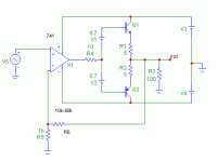
Hi, PMA,The circuit I have just posted is a good example of IMPROPER use of NFB
What is "improper" about the sch you draw above? I cannot see the "improper" thing.
lamanauw,
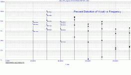
please review the image with loopgain and closed loop gain vs. frequency. This is the typical improper use of feedback.
The second problem is slew rate of the LM741. It is about 0.5V/us and it gives slew distortion as soon as at 1OVp/8kHz.
http://www.diyaudio.com/forums/showthread.php?postid=1280631#post1280631
Hi, PMA,
I think I get it 😀 The loop gain is not enough (smaller than closed loop gain), starting 100hz above? Not enough gain to be burned by feedback.
I think I get it 😀 The loop gain is not enough (smaller than closed loop gain), starting 100hz above? Not enough gain to be burned by feedback.
NO PMA, you do NOT have a really problem with overbiasing, here. You have the choice of the WRONG VALUE of emitter resistor. Run the sim again with .15 ohms like I use. Check it out! Poor design is poor design. Bob did this, on purpose to see what happens, but it is UNDERBIASING that will show the potential problems of feedback.
If I get you right PMA, feedback fixes just about everything, so why bother with anything else?
If I get you right PMA, feedback fixes just about everything, so why bother with anything else?
john curl said:NO PMA, you do NOT have a really problem with overbiasing, here. You have the choice of the WRONG VALUE of emitter resistor.
I have never said it is a correct value of the emitter resistor. And it is no really used design. You seem not to understand me, John.
Hi Andy,
I wonder if you could add a frequency dependent loopgain into your simulations. It might bring interesting results.
I wonder if you could add a frequency dependent loopgain into your simulations. It might bring interesting results.
- Home
- Amplifiers
- Solid State
- Bob Cordell Interview: Negative Feedback


