I found the irregularity on 3rd harmonic in a circuit with opamp and AB transistor output stage as well, as a function of loopgain. Distortion not decreasing with increasing loopgain for certain values, and similar dip. I have it on another computer, maybe tommorow.
andy_c said:If I really wanted AC coupling, I'd need to make the coupling cap as small as I can get away with, then run the sim long enough for the voltage on the cap to change to its final value. I'm going to try DC coupling for now.
Hi Andy,
You can get rid of this by setting the FFT DSP up in such a way that is uses only the last quarter of the transient run, provided the run is long enough. But it is best to avoid any capacitor to avoid low frequency leaking caused by DC charging the caps.
😉
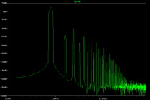
It is quite normal to let FFT run e.g. 10 cycles and to analyze the last one. Analyzing the 1st one there is almost always an error of analyzing the initial transient.
In the attached image, one can see that first 4 cycles are thrown away and the 5th is analyzed.
In the attached image, one can see that first 4 cycles are thrown away and the 5th is analyzed.
Attachments
Good Bob, all that I care about is that we are on the same page. Also, it is important that the distortion mechanisms are better understood by all. I was amazed when I first realized these interactions. It is especially important with tube circuits.
Pjotr said:You can get rid of this by setting the FFT DSP up in such a way that is uses only the last quarter of the transient run, provided the run is long enough. But it is best to avoid any capacitor to avoid low frequency leaking caused by DC charging the caps.
Hi Pjotr,
It turns out the default behavior of LTSpice using the "dot FOUR" directive is to do an FFT of the last cycle without any user intervention. What I was getting at is that the sim has to run long enough for any transient to settle out. If I wanted true AC coupled feedback, I'd have to run lots of cycles for a 1 Farad cap to change its DC voltage by a Volt or so into a 100k load. I'm making a wild guess that the DC component of the distortion is about 1 Volt due to even-order effects. This was in the no-feedback case where gross distortion was present.
PMA said:It is quite normal to let FFT run e.g. 10 cycles and to analyze the last one. Analyzing the 1st one there is almost always an error of analyzing the initial transient.
Yes. In my case I was running the sim for 20 msec (1 kHz sine). I am using the "dot FOUR" directive with LTSpice. The LTSpice docs say this about the behavior of "dot FOUR".
"The Fourier analysis is performed over the period from the final time, Tend, to one period before Tend unless an integer Nperiods is given after Nharmonics."
john curl said:Good Bob, all that I care about is that we are on the same page. Also, it is important that the distortion mechanisms are better understood by all. I was amazed when I first realized these interactions. It is especially important with tube circuits.
I agree, John. I think we are all learning something from this exercise. Sometimes when we pursue something, not even knowing where it may lead, we may learn something we hadn't even been expecting.
Do you think that these interactions are the primary reason for the sound of tubes?
BTW, about 18 months ago I rebuilt a tube amp I had built in college. Complete re-do and re-design. I did it because I wanted to compare tube sound with some solid state amps using a tube amp I understood (also, too cheap to buy one). I learned a lot in doing my first tube design in about 35 years. BTW it is pretty much a classic design using typical amounts of feedback and achieving typical tube damping factor of less than 20. I used to hate the output transformers, of course. However, in my fooling around I think I gained some understanding of their role in making the tube sound. I ended up with the impression that the core saturation effect in the output transformers may also be partly responsible for the softer clipping. Just a thought. They are fascinating.
Cheers,
Bob
andy_c said:
Yes. In my case I was running the sim for 20 msec (1 kHz sine). I am using the "dot FOUR" directive with LTSpice. The LTSpice docs say this about the behavior of "dot FOUR".
"The Fourier analysis is performed over the period from the final time, Tend, to one period before Tend unless an integer Nperiods is given after Nharmonics."
I ran my sims for 40 ms and analyzed the last 8 ms. Probably overkill, but with only one transistor they still didn't take too long.
Bob
Hi Andy,
Than your only alternative is not to use time dependant components like capacitors and inductors.
I myself prefer Microcap9. It is much more user friendly than LT-Spice IMO. The free student edition has plenty of power to investigate the topic at hand.
😉
Than your only alternative is not to use time dependant components like capacitors and inductors.
I myself prefer Microcap9. It is much more user friendly than LT-Spice IMO. The free student edition has plenty of power to investigate the topic at hand.
😉
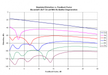
Bob Cordell said:Secondly, and more seriously, I think Baxandall's inclusion of 1k source impedance in the base circuit really can cloud the issue. At his operating current of 1.55 mA, re is just 16.8 ohms. If he has a beta of 100, he is looking at 1700 ohms looking into the base, way not insignificant compared to his source impedance. I just naturally assumed that if we wanted to see the true behavior of feedback in a situation like this, we would want the base of the CE stage voltage driven. Anyway, its not really right or wrong, its just a difference that could strongly influence the results.
Bingo! That was it. I removed the base resistor network and drove the base with a voltage source. The base spreading resistance in the 2N5551 model is 10 Ohms. I now have a very pronounced dip in the 3rd order distortion component at 3 dB feedback. Here's the new plot, again with 1 dB steps from 0 dB to 30 dB feedback.
Attachments
andy_c said:
Bingo! That was it. I removed the base resistor network and drove the base with a voltage source. The base spreading resistance in the 2N5551 model is 10 Ohms. I now have a very pronounced dip in the 3rd order distortion component at 3 dB feedback. Here's the new plot, again with 1 dB steps from 0 dB to 30 dB feedback.
Excellent!!!
Bob
I must also express gratitude for the last few pages. It was a wake-up call for me, having rather hated maths at varsity and gone on to prefer designing in a hologistic way. I was fortunate to have had excellent spectrum analysers at my disposal until I retired about a decade ago.
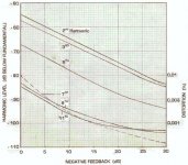
I have a set of plots for a complete amplifier, both simulated and measured. (I think it was Pinkmouse who asked for the simulation of a more complete am[plifier.) If the differences seem to puzzle some members, remember this is a complete amplifier, not just one stage. Thus no contradiction to above posts is inferred; there was nothing in those contributions that I have issue with.
Some nested feedback was active at no global NFB, e.g. the differential input stage (used in inverting mode) and the full complimentary output configuration. I also recall that NFB was applied in increments of 5dB, and as soon as there is time I will examine the first say 6dB with greater resolution given the above discussion. I doubt however that severe deviations will appear, unless I have been so singularly lucky to have just by chance picked all the points through which a straight line oor smooth curve passed. (The graphs were not smoothed, points were within a dB or so of the plots shown.) Flattening off in the slopes of higher order harmonics is clearly visible. The odd behaviour of the 7th harmonic was not investigated.
The practical measurements were somewhat off but the same tendencies occurred, which is the reason for showing it here. (The transistors used were different from the simulation models.) Incidentally, I also found emitter resistors to cause distortion, which was the reason for avoiding them, even in the power stage.
The circuit was for an 80W amplifier; graphs were taken at 40W output into 8 ohms resistive.
Attachments
I forgot to add, kindly excuse the rather blotchy captions. The diagram was assembled from a picture on graph paper, not pc drawn.
Bob Cordell said:
I also wish I had a SPICE model for the actual transistor that Baxandall used.
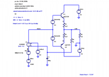
Slim chances that this one even resembles...,... it's a Zetex part from Isis (Proteus 6.4 - Lite)
I hope this helps...
Attachments
andy_c said:
One possible explanation for decreasing open-loop distortion with increasing frequency might be that he uses so many output devices, that the VAS distortion, which decreases with increasing frequency (due to Miller comp) is actually dominating over output stage distortion over some of the frequency range.
But yes, it does indicate very good open-loop linearity and a great job by John all around.
I too get fed up with the often repeated false dichotomy implying that high-feedback designs must have high open-loop distortion. It's much easier and less time-consuming to mindlessly repeat something than to properly explain it. That's why people who carefully explain things end up getting the short end of the stick in the propaganda wars around here.
Although it is hard to explain the measured results without knowing the exact details of the circuit, decreasing VAS distortion with frequency does seem plausible – but it would have to be a VAS with a significant amount of non-linearity to dominate to such a degree.
Also, I don’t think that the Stereophile measurements indicate an amplifier with particularly high open loop linearity. The 2,4 and 8 ohm THD plots are done at a load voltage of only 12.5V. This isn’t a very stringent test IMO, considering the fact that the amplifier has a high class AB bias and a ‘continuous’ power rating of 800W into 4 ohms.
Below 1kHz, the 2,4 and 8 ohm 12.5V THD plots are generally above 0.01%. If we assume a negative feedback factor of around 40dB below 1kHz, then the open loop distortion must be in excess of 1%. And this is at only 12.5V. Stereophiles 1kHz pulse testing reveals –70dB THD at 500W (0.03%) – so ~3% OL THD. Parasound specifies 20kHz THD at no more than 0.15%. This fits in reasonably well with 40dB of LF negative feedback and an open loop bandwidth of 4kHz (giving 26db NFB at 20kHz) – 20(26dB)*0.15 = 3% OL THD.
This seems to suggest against a fall in OL THD with frequency at high power. Since VAS linearity generally degrades somewhat exponentially with signal swing though, this doesn’t rule out your explanation for the measured THD vs. frequency behaviour at low power.
EDIT: Also, 0.15% (500W THD-20) / 0.03% (measured 500W THD @ 1kHz) = 5 - exactly as one would expect.
Cheers,
Glen
Class-AB Output Stage Dist vs NFB
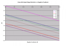
Most would agree that the Class-AB output stage is perhaps the most insidious source of distortion, i.e., it's crossover distortion. It is among the most difficult to completely get rid of and it creates a spray of high harmonics.
For that reason, I have run the simulation for distortion components as a function of applied NFB for a Class-AB output stage.
The stage uses a single pair of MJL21193, MJL21194 output devices, each with a 0.47 ohm RE and feeding an 8-ohm load. The stage is biased at 152 mA idle current, so that there is 71 mV across each RE (as opposed to the optimum of 26 mV). This is deliberately over-biased, into the gm-doubling range a bit, so as to produce moderate crossover distortion. In addition, of course, the use of 0.47 ohm RE is a bit more than normal, once again highlighting the crossover distortion.
The results are really interesting, to say the least. For this kind of insidious distortion, the application of negative feedback decreases all harmonic components consistently and monotonically as feedback is applied and increased.
Here appears to be a very important case where the application of NFB does not introduce or enhance any distortion components.
Cheers,
Bob
Attachments
- Home
- Amplifiers
- Solid State
- Bob Cordell Interview: Negative Feedback