andy_c said:I just tried a sim of Baxandall's BJT circuit with feedback factor from 0 dB to 30 dB in 1 dB steps. Here is the graph I came up with. I'll just post it without comment.
Hi Andy,
Nice work!
First, I wish I could manipulate SPICE as well as you do!!
Your results obviously differ from mine, and both our results differ from Baxandall's. But all three show the same kind of general behavior.
The first place I looked at differences was the distortion with no negative feedback. Obviously, if that is not the same, the results with increasing amounts of applied feedback will also differ.
So, why do your results differ from mine? My guess is that we are using different transistor models, or maybe even different transistors. If I had to guess about which parameter it might be, I'd be tempted to say it might be the amount of Early Effect, but that is just a wild guess.
It is also possible that we are using slightly different simulation circuits or slightly different operating points. I tried to duplicate Baxandall's as closely as possible, but I could have been in error. I have also used a different transistor than Baxandall's BC183C.
Of course, anybody who seriously designs amplifiers knows that different transistors will give slightly different distortion results. Duh!
And we also know that there are different SPICE models out there, which can either translate to effectively different transistors or to differences as a result of model imperfections.
We all know SPICE and its application is not perfect, but we also know that, wisely used and with all caveats in mind, it can be a tremendously helpful tool in our overstuffed toolbox. It is no substitute for a prototype circuit and a distortion analyzer.
Let's also not lose site of the original question that was posed here, namely whether the application of NFB increases certain distortion components under some conditions, such as relatively low amounts of NFB. That we have shown, even if the details are a bit different among the two simulations and Baxandall's measurements. That is a good thing.
We have also gained insight as to under what conditions the application of NFB does not create enhancement of any distortion components. That is also potentially quite valuable.
Cheers,
Bob
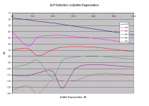
BJT Distortion with Emitter Degeneration
Below I have posted the results for single-ended BJT distortion as a function of emitter degeneration with no "Global" NFB. The amount of emitter degeneration is expressed in dB in the same way as was the Baxandall "global" NFB placed "around" the stage.
Note that I have now added a data point for a value corresponding to about 3 dB of degeneration.
The results are nearly identical to the results I presented earlier for feedback around the stage.
I guess that this should probably come as no surprize, but it is nevertheless very interesting to see. It shows that local emitter degeneration is no more benign in its effects on distortion than "global" feedback around the stage - all of the effects of enhancement of certain distortion spectra by the local NFB are still there, and numerically pretty much the same.
So if you don't like NFB around a stage, you should equally not like emitter degeneration.
It also suggests that the total amount of NFB created by degeneration and feedback around a stage is what counts, and that the magic number that pretty much gets you in the clear of enhancement for spectra no lower than -109 dB out to the 7th is on the order of 20 dB.
Cheers,
Bob
Attachments
pinkmouse said:
I was thinking of the Baxandall stuff that was quoted earlier. Okay, maybe a better challenge, can we build something to test distortion at -160dB?
I can see distortion components in power amplifiers down to at least the mid-140's using a combination of my Distortion Magnifier, my THD analyzer, and my spectrum analyzer.
Bob
Bob, if you would change the part to something more suitable for the actual circuit, I think that you will get it exactly. The 2N5551 has too much emitter resistance, probably because it is a very high voltage part. Check out a 2N4401 in this application, for example. It has less than 1/2 the emitter resistance of the 2N5551. This should make it track better, and probably increase the 3'rd harmonic null.
john curl said:Bob, if you would change the part to something more suitable for the actual circuit, I think that you will get it exactly. The 2N5551 has too much emitter resistance, probably because it is a very high voltage part. Check out a 2N4401 in this application, for example. It has less than 1/2 the emitter resistance of the 2N5551. This should make it track better, and probably increase the 3'rd harmonic null.
Hi John,
Good thought, thanks for the suggestion. I'll try to give it a look tonight.
But here is a question: if I do it in regard to the plot I just showed, where the variable was emitter degeneration (and where the 3rd harmonic notch was visible because I included the 3 dB data point), wouldn't effects of the BJT emitter resistance be the same as sliding the set of curves a bit left or right, since the emitter degeneration variable was put in by introducing external emitter resistance?
I also wish I had a SPICE model for the actual transistor that Baxandall used.
Cheers,
Bob
pooge said:why not try the OnSemi models that AndyC provided the SPICE models for?
I thought those were just for the power transistors.
Bob
Are we having fun yet? 
Hi Bob,
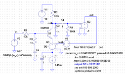
I noticed you were using the 2N5551, so I used that also. The model I used originally came from Fairchild I believe. Here is the model:
.model 2N5551 NPN(Is=2.511f Xti=3 Eg=1.11 Vaf=100 Bf=242.6 Ne=1.249 Ise=2.511f Ikf=.3458 Xtb=1.5 Br=3.197 Nc=2 Isc=0 Ikr=0 Rc=1 Cjc=4.883p Mjc=.3047 Vjc=.75 Fc=.5 Cje=18.79p Mje=.3416 Vje=.75 Tr=1.202n Tf=560p Itf=50m Vtf=5 Xtf=8 Rb=10 Vceo=160 Icrating=600m mfg=Fairchild)
There is no RE called out, so it gets the default value of 0.
My circuit config is also somewhat different. I've attached the schematic below. The first thing I noticed when I ran the sim without feedback was that there was gross distortion and waveform asymmetry, with a significant DC shift due to the high even-order distortion. As Baxandall predicts, just the second order term alone is over 10 percent. I noticed that Baxandall AC coupled his feedback, so I did the same. If the feedback were DC coupled, you'd have the DC shift due to the even-order distortion, plus another DC shift (opposite direction maybe?) due to the DC component of the feedback signal.
For the bias, I just used a 1.45 mA current source in the emitter, bypassed by a 1F capacitor. I put Baxandall's resistor network at the input, but the capacitor is also the silly 1F value.
The voltage source V3 is there just to measure the loop gain. Since it's between a 0 Ohm source and an open-circuit load, the simplified loop gain technique from the LTSpice audioamp.asc example will be accurate, and the full loop gain probe is not needed.
The VCVS of value "k" in the emitter provides the feedback. I computed the loop gain for k=1, so that, assuming linearity and loop gain proportional to k, it's easy to compute k for any desired value of loop gain.
I put together a spreadsheet, starting with a column for feedback factor going from 0 to 30 dB in 1 dB steps. For each one, I convert to a voltage ratio and subtract 1 to get the loop gain. For each loop gain, I compute k. So for each feedback factor, I end up with the k value needed to get the desired loop gain. I then did a stepped small-signal AC analysis for each k value using .STEP PARAM k LIST, with the list of k values pasted from the spreadsheet. I get the gain for each k by selecting only one step at a time in the graph display and reading each value from the graph. I compute the input signal amplitude from Baxandall's 3 Volt peak divided by the simulated small-signal gain. This ends up being pretty accurate even though linearity is violated. More on this in a moment.
Based on this, for each feedback factor, I now have a k value and an input amplitude. I do a distortion sim using transient with .FOUR using each of these values. Choosing View, SPICE error log, I get all the harmonics and copy and paste them into the spreadsheet. The columns are tab-delimited in the error log, so this works nicely. The error log also displays the peak value of the fundamental component of the output, which I check against the desired 3 Volt value. The linearity assumption is surprisingly close even for the high distortion case, and gets better as the distortion decreases. Trying to get the input amplitude in transient would take forever, and for the high-distortion case may not be very accurate anyway. Once I do all 31 sims, I end up with a table in the spreadsheet having harmonic voltage amplitudes expressed as a ratio to the fundamental. I just create another table with formulas to convert these to dB.
Anyway, that's my story and I'm stickin' to it
Bob Cordell said:Your results obviously differ from mine, and both our results differ from Baxandall's. But all three show the same kind of general behavior.
The first place I looked at differences was the distortion with no negative feedback. Obviously, if that is not the same, the results with increasing amounts of applied feedback will also differ.
So, why do your results differ from mine? My guess is that we are using different transistor models, or maybe even different transistors. If I had to guess about which parameter it might be, I'd be tempted to say it might be the amount of Early Effect, but that is just a wild guess.
It is also possible that we are using slightly different simulation circuits or slightly different operating points. I tried to duplicate Baxandall's as closely as possible, but I could have been in error. I have also used a different transistor than Baxandall's BC183C.
Hi Bob,
I noticed you were using the 2N5551, so I used that also. The model I used originally came from Fairchild I believe. Here is the model:
.model 2N5551 NPN(Is=2.511f Xti=3 Eg=1.11 Vaf=100 Bf=242.6 Ne=1.249 Ise=2.511f Ikf=.3458 Xtb=1.5 Br=3.197 Nc=2 Isc=0 Ikr=0 Rc=1 Cjc=4.883p Mjc=.3047 Vjc=.75 Fc=.5 Cje=18.79p Mje=.3416 Vje=.75 Tr=1.202n Tf=560p Itf=50m Vtf=5 Xtf=8 Rb=10 Vceo=160 Icrating=600m mfg=Fairchild)
There is no RE called out, so it gets the default value of 0.
My circuit config is also somewhat different. I've attached the schematic below. The first thing I noticed when I ran the sim without feedback was that there was gross distortion and waveform asymmetry, with a significant DC shift due to the high even-order distortion. As Baxandall predicts, just the second order term alone is over 10 percent. I noticed that Baxandall AC coupled his feedback, so I did the same. If the feedback were DC coupled, you'd have the DC shift due to the even-order distortion, plus another DC shift (opposite direction maybe?) due to the DC component of the feedback signal.
For the bias, I just used a 1.45 mA current source in the emitter, bypassed by a 1F capacitor. I put Baxandall's resistor network at the input, but the capacitor is also the silly 1F value.
The voltage source V3 is there just to measure the loop gain. Since it's between a 0 Ohm source and an open-circuit load, the simplified loop gain technique from the LTSpice audioamp.asc example will be accurate, and the full loop gain probe is not needed.
The VCVS of value "k" in the emitter provides the feedback. I computed the loop gain for k=1, so that, assuming linearity and loop gain proportional to k, it's easy to compute k for any desired value of loop gain.
I put together a spreadsheet, starting with a column for feedback factor going from 0 to 30 dB in 1 dB steps. For each one, I convert to a voltage ratio and subtract 1 to get the loop gain. For each loop gain, I compute k. So for each feedback factor, I end up with the k value needed to get the desired loop gain. I then did a stepped small-signal AC analysis for each k value using .STEP PARAM k LIST, with the list of k values pasted from the spreadsheet. I get the gain for each k by selecting only one step at a time in the graph display and reading each value from the graph. I compute the input signal amplitude from Baxandall's 3 Volt peak divided by the simulated small-signal gain. This ends up being pretty accurate even though linearity is violated. More on this in a moment.
Based on this, for each feedback factor, I now have a k value and an input amplitude. I do a distortion sim using transient with .FOUR using each of these values. Choosing View, SPICE error log, I get all the harmonics and copy and paste them into the spreadsheet. The columns are tab-delimited in the error log, so this works nicely. The error log also displays the peak value of the fundamental component of the output, which I check against the desired 3 Volt value. The linearity assumption is surprisingly close even for the high distortion case, and gets better as the distortion decreases. Trying to get the input amplitude in transient would take forever, and for the high-distortion case may not be very accurate anyway. Once I do all 31 sims, I end up with a table in the spreadsheet having harmonic voltage amplitudes expressed as a ratio to the fundamental. I just create another table with formulas to convert these to dB.
Anyway, that's my story and I'm stickin' to it
Attachments
I think that the SPICE model for the 2N5551 is somewhat inaccurate. This is based on looking at REAL curves in the Motorola handbook. So now, we are back to lousy models and other problems.
Gentlemen,
I bow for you! This is all extremely interesting and very smart work.
I would very much like to contribute, but I am afraid I will need to leave it at this question and idea for answer:
Does anyone have an idea why the distortion curves have those ripples? Could it be a (phase) cancellation effect between the "organic" harmonic component resulting from the device non-linearity and the 'created' harmonic component from the feedback signal intermodulating the individual components?
Jan Didden
Jan, the reason for the ripples is that there is both expanding and contracting distortion. Think about an analog tape recorder. It has all contracting third harmonic distortortion in normal operation.
However, transistors have EXPANDING third, when there is no feedback. The CONTRACTING third harmonic is generated from the second harmonic and the feedback. That is why it is supposed to NULL at 3dB feedback. More feedback always gives contracting third. When I do not see this NULL, I know that the simulation is flawed.
However, transistors have EXPANDING third, when there is no feedback. The CONTRACTING third harmonic is generated from the second harmonic and the feedback. That is why it is supposed to NULL at 3dB feedback. More feedback always gives contracting third. When I do not see this NULL, I know that the simulation is flawed.
john curl said:Jan, the reason for the ripples is that there is both expanding and contracting distortion. Think about an analog tape recorder. It has all contracting third harmonic distortortion in normal operation.
However, transistors have EXPANDING third, when there is no feedback. The CONTRACTING third harmonic is generated from the second harmonic and the feedback. That is why it is supposed to NULL at 3dB feedback. More feedback always gives contracting third. When I do not see this NULL, I know that the simulation is flawed.
OooKee... Contracting with increase of feedback I can understand. When you say expanding I guess it is expanding as a result of something? Do you mean as a result of higher input levels with higher feedback for the same output level? Or did I turn off at the wrong intersection?
Jan Didden
Re: BJT Distortion with Emitter Degeneration
Feedback is feedback. I do not why so many "audio designers" differ between "global" and "local" NFB, and, do not consider Emitter resistor as feedback at all!!
Instead of that, they should better take into account what means voltage feedback, current feedback, parallel feedback and serial feedback. It speaks about gain, Zin, Zout - and distortion.
Bob Cordell said:Below I have posted the results for single-ended BJT distortion as a function of emitter degeneration with no "Global" NFB.
The results are nearly identical to the results I presented earlier for feedback around the stage.
I guess that this should probably come as no surprize, but it is nevertheless very interesting to see. It shows that local emitter degeneration is no more benign in its effects on distortion than "global" feedback around the stage - all of the effects of enhancement of certain distortion spectra by the local NFB are still there, and numerically pretty much the same.
So if you don't like NFB around a stage, you should equally not like emitter degeneration.
I
Feedback is feedback. I do not why so many "audio designers" differ between "global" and "local" NFB, and, do not consider Emitter resistor as feedback at all!!
Instead of that, they should better take into account what means voltage feedback, current feedback, parallel feedback and serial feedback. It speaks about gain, Zin, Zout - and distortion.
janneman said:Gentlemen,
I bow for you! This is all extremely interesting and very smart work.
I would very much like to contribute, but I am afraid I will need to leave it at this question and idea for answer:
Does anyone have an idea why the distortion curves have those ripples? Could it be a (phase) cancellation effect between the "organic" harmonic component resulting from the device non-linearity and the 'created' harmonic component from the feedback signal intermodulating the individual components?
Jan Didden
Hi Jan,
YES.
Bob
john curl said:When I do not see this NULL, I know that the simulation is flawed.
Hi John,
But you DID see the 23 dB null in third in my latest simulation when I included the 3 dB feedback degeneration data point, right?
By the way, thank you for bringing to my attention that null and getting me to add that additional data point. My earlier sims without the 3 dB NFB data point obviously missed part of the story.
Bob
Re: Re: BJT Distortion with Emitter Degeneration
Well that is a whole other area. Lets stick to what feedback basically does, whether or not global or local. For that the accuracy of the transistor models are not that important. It is important that the transfer function of the open-loop gain is not linear and as such generates higher harmonics.
If you want to investigate what feedback does with regard to harmonics there is no need to use actual transistor models. Simply use a non-linear transfer function for the open-loop gain like: a * (1+b^c) and bias it properly. Put it in Pspice and fiddle around wit a, b and c
Pspice by itself is nothing else than an iterative numeric equation solver. By that it is a reliable tool to make such things visible.
Cheers 😉
PMA said:Instead of that, they should better take into account what means voltage feedback, current feedback, parallel feedback and serial feedback. It speaks about gain, Zin, Zout - and distortion.
Well that is a whole other area. Lets stick to what feedback basically does, whether or not global or local. For that the accuracy of the transistor models are not that important. It is important that the transfer function of the open-loop gain is not linear and as such generates higher harmonics.
If you want to investigate what feedback does with regard to harmonics there is no need to use actual transistor models. Simply use a non-linear transfer function for the open-loop gain like: a * (1+b^c) and bias it properly. Put it in Pspice and fiddle around wit a, b and c
Pspice by itself is nothing else than an iterative numeric equation solver. By that it is a reliable tool to make such things visible.
Cheers 😉
andy_c said:Are we having fun yet?
Hi Bob,
I noticed you were using the 2N5551, so I used that also. The model I used originally came from Fairchild I believe. Here is the model:
.model 2N5551 NPN(Is=2.511f Xti=3 Eg=1.11 Vaf=100 Bf=242.6 Ne=1.249 Ise=2.511f Ikf=.3458 Xtb=1.5 Br=3.197 Nc=2 Isc=0 Ikr=0 Rc=1 Cjc=4.883p Mjc=.3047 Vjc=.75 Fc=.5 Cje=18.79p Mje=.3416 Vje=.75 Tr=1.202n Tf=560p Itf=50m Vtf=5 Xtf=8 Rb=10 Vceo=160 Icrating=600m mfg=Fairchild)
There is no RE called out, so it gets the default value of 0.
My circuit config is also somewhat different. I've attached the schematic below. The first thing I noticed when I ran the sim without feedback was that there was gross distortion and waveform asymmetry, with a significant DC shift due to the high even-order distortion. As Baxandall predicts, just the second order term alone is over 10 percent. I noticed that Baxandall AC coupled his feedback, so I did the same. If the feedback were DC coupled, you'd have the DC shift due to the even-order distortion, plus another DC shift (opposite direction maybe?) due to the DC component of the feedback signal.
For the bias, I just used a 1.45 mA current source in the emitter, bypassed by a 1F capacitor. I put Baxandall's resistor network at the input, but the capacitor is also the silly 1F value.
The voltage source V3 is there just to measure the loop gain. Since it's between a 0 Ohm source and an open-circuit load, the simplified loop gain technique from the LTSpice audioamp.asc example will be accurate, and the full loop gain probe is not needed.
The VCVS of value "k" in the emitter provides the feedback. I computed the loop gain for k=1, so that, assuming linearity and loop gain proportional to k, it's easy to compute k for any desired value of loop gain.
I put together a spreadsheet, starting with a column for feedback factor going from 0 to 30 dB in 1 dB steps. For each one, I convert to a voltage ratio and subtract 1 to get the loop gain. For each loop gain, I compute k. So for each feedback factor, I end up with the k value needed to get the desired loop gain. I then did a stepped small-signal AC analysis for each k value using .STEP PARAM k LIST, with the list of k values pasted from the spreadsheet. I get the gain for each k by selecting only one step at a time in the graph display and reading each value from the graph. I compute the input signal amplitude from Baxandall's 3 Volt peak divided by the simulated small-signal gain. This ends up being pretty accurate even though linearity is violated. More on this in a moment.
Based on this, for each feedback factor, I now have a k value and an input amplitude. I do a distortion sim using transient with .FOUR using each of these values. Choosing View, SPICE error log, I get all the harmonics and copy and paste them into the spreadsheet. The columns are tab-delimited in the error log, so this works nicely. The error log also displays the peak value of the fundamental component of the output, which I check against the desired 3 Volt value. The linearity assumption is surprisingly close even for the high distortion case, and gets better as the distortion decreases. Trying to get the input amplitude in transient would take forever, and for the high-distortion case may not be very accurate anyway. Once I do all 31 sims, I end up with a table in the spreadsheet having harmonic voltage amplitudes expressed as a ratio to the fundamental. I just create another table with formulas to convert these to dB.
Anyway, that's my story and I'm stickin' to it
Hi Andy,
I'm breathless after reading your post here. You are amazing!
I can see some possible reasons why our sims may differ, and why my sim differs from Baxandall's.
First, I used the same model for the 2N5551.
You were a bit more faithful in copying Baxandall's arrangement, warts and all.
Here are two concerns I have with his arrangement that you also used:
First, he has a 1000 pF LPF in his collector circuit. This may not be too big a deal, but it looks like it gives a pole at about 50 kHz, less than a decade above the 7th harmonic. Its conceivable that there may be some minor phase effects as a result. I left it out completely. I imagine that even in the real world he would only have needed 100 pF there for stability. But who knows, those op amps he was using ...
Secondly, and more seriously, I think Baxandall's inclusion of 1k source impedance in the base circuit really can cloud the issue. At his operating current of 1.55 mA, re is just 16.8 ohms. If he has a beta of 100, he is looking at 1700 ohms looking into the base, way not insignificant compared to his source impedance. I just naturally assumed that if we wanted to see the true behavior of feedback in a situation like this, we would want the base of the CE stage voltage driven. Anyway, its not really right or wrong, its just a difference that could strongly influence the results.
I understand that it is also a philosophical decision as to whether the feedback should be dc coupled or ac coupled in this situation. I chose dc coupling and the dc component of the second harmonic could affect the operating point a bit, although I did not see much evidence of a dc shift. Note that a huge percentage of the time when we are just looking at emitter degeneration, the "loop" is dc coupled by definition. So I am inclined to believe my recent results as a function of emitter degeneration in that regard.
Cheers,
Bob
Re: Re: BJT Distortion with Emitter Degeneration
I would think that Charles Hansen might have a comment or some insight on this at this point.
Cheers,
Bob
PMA said:
Feedback is feedback. I do not why so many "audio designers" differ between "global" and "local" NFB, and, do not consider Emitter resistor as feedback at all!!
I would think that Charles Hansen might have a comment or some insight on this at this point.
Cheers,
Bob
Bob Cordell said:Secondly, and more seriously, I think Baxandall's inclusion of 1k source impedance in the base circuit really can cloud the issue. At his operating current of 1.55 mA, re is just 16.8 ohms. If he has a beta of 100, he is looking at 1700 ohms looking into the base, way not insignificant compared to his source impedance. I just naturally assumed that if we wanted to see the true behavior of feedback in a situation like this, we would want the base of the CE stage voltage driven. Anyway, its not really right or wrong, its just a difference that could strongly influence the results.
I understand that it is also a philosophical decision as to whether the feedback should be dc coupled or ac coupled in this situation. I chose dc coupling and the dc component of the second harmonic could affect the operating point a bit, although I did not see much evidence of a dc shift. Note that a huge percentage of the time when we are just looking at emitter degeneration, the "loop" is dc coupled by definition. So I am inclined to believe my recent results as a function of emitter degeneration in that regard.
Good ideas there. I am going to try changing some things per your concerns. Specifically, I still can't get the dip to show up in the third harmonic. That points to you being right and me being wrong. The base resistor seems a good place to start.
Also, I realized that my feedback is, in effect, DC also. I have a 1F coupling capacitor in the loop. LOL! See the problem? In order to get the DC distortion component removed, the capacitor needs to have enough time for its DC voltage to change during the simulation. That, ummm, takes a while with a 1F capacitor and 100k 🙂. It's like a battery, and I'm running the sim for only 20 msec. If I really wanted AC coupling, I'd need to make the coupling cap as small as I can get away with, then run the sim long enough for the voltage on the cap to change to its final value. I'm going to try DC coupling for now.
- Home
- Amplifiers
- Solid State
- Bob Cordell Interview: Negative Feedback