EC
Hi Forr,
Now, connect the non-inverting input of the output stage to node Y, instead of X. See what I mean?
Cheers,
Edmond.
Hi Forr,
Now, connect the non-inverting input of the output stage to node Y, instead of X. See what I mean?
Cheers,
Edmond.
I was “inspired” by a recent comment by Scott Wurcer in the Blowtorch thread:
I highly respect Scott's work but I am “one of those people” – My belief is that the AD797 distortion cancellation scheme is an interesting local feedback circuit that increases loop gain, as detectable by appropriate measurement of Bode's return difference T
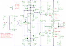
I believe this sim captures the topology of the AD797 as presented in the data sheet description of the error correction scheme – obviously the transistor models and bias are crude approximations but the circuit appears to have plausible performance
in order to plot comparative graphs the circuit is duplicated and the Tain bilateral Loop Gain Probe is inserted in each
green is the measured loop gain with the 50 pF Cn distortion cap in place, red is with the value reduced to negligible level – both circuits with external feedback setting Av=10
over the ~1KHz to 1MHz region Scott's “distortion cancellation by simple subtraction” is readily visible as an added 20 dB of loop gain
the usual cost of higher loop gain is the reduced phase margin where the gain has to roll off faster than 1-pole, in this instance the cost is very neatly compensated by the lower slope of the gain curve just past the 0 dB gain intercept (higher intercept frequency with the distortion cancelation C helps too)
which isn't exactly the same as the AD797 data sheet claim: "Therefore, the distortion cancellation does not affect the stability or frequency response of the amplifier"

the circuit was a pain to get started - bias point calculations seem to fail more often in LtSpice with very high gain circuits
I reduced Tools>Control Panel>Spice tolerance settings until some bias point was found, then I used the .savebias/.loadbais directives to get it to start up with default Spice accuracy settings
scott wurcer said:
>Scott,
>
>In a sense, that 797 is too smart for its own good. How many >application designers realise/understand that capacitive error >correction?
>
>Jan Didden
In the beginning I never knew why anyone would want 1nV at gain of one. The part was designed for ATE and other instrument use, the rest was for fun. The rbb on the input devices was reduced below a critical threshold for the ft on this process, the "10 turns of wire on a resistor" input snubbers work best but marketing forbid this on the data sheet.
BTW I got the brush-off at the AES conference from DR. L, I guess I wasn't an insider. Also someone tracked me down to say that the distortion neutralization "had to be just feedback in disguse". Where have I heard that before?
I highly respect Scott's work but I am “one of those people” – My belief is that the AD797 distortion cancellation scheme is an interesting local feedback circuit that increases loop gain, as detectable by appropriate measurement of Bode's return difference T
I believe this sim captures the topology of the AD797 as presented in the data sheet description of the error correction scheme – obviously the transistor models and bias are crude approximations but the circuit appears to have plausible performance
in order to plot comparative graphs the circuit is duplicated and the Tain bilateral Loop Gain Probe is inserted in each
green is the measured loop gain with the 50 pF Cn distortion cap in place, red is with the value reduced to negligible level – both circuits with external feedback setting Av=10
over the ~1KHz to 1MHz region Scott's “distortion cancellation by simple subtraction” is readily visible as an added 20 dB of loop gain
the usual cost of higher loop gain is the reduced phase margin where the gain has to roll off faster than 1-pole, in this instance the cost is very neatly compensated by the lower slope of the gain curve just past the 0 dB gain intercept (higher intercept frequency with the distortion cancelation C helps too)
which isn't exactly the same as the AD797 data sheet claim: "Therefore, the distortion cancellation does not affect the stability or frequency response of the amplifier"
the circuit was a pain to get started - bias point calculations seem to fail more often in LtSpice with very high gain circuits
I reduced Tools>Control Panel>Spice tolerance settings until some bias point was found, then I used the .savebias/.loadbais directives to get it to start up with default Spice accuracy settings
Attachments
Re: EC
Hi Edmond,
You may think of the influence of the non-linearities of the input of the output stage on the source. Y having a lower impedance than X, you should mean lower distorsion.
Since Jan's publication, I started to read the whole thread with greater attention than previously, you may have already written something on this scheme but I did not find it yet.
Regards
Edmond Stuart said:
Now, connect the non-inverting input of the output stage to node Y, instead of X. See what I mean?
Hi Edmond,
You may think of the influence of the non-linearities of the input of the output stage on the source. Y having a lower impedance than X, you should mean lower distorsion.
Since Jan's publication, I started to read the whole thread with greater attention than previously, you may have already written something on this scheme but I did not find it yet.
Regards
Re: Re: EC
Hi Forr,
Perhaps I was a bit cryptic, but I'm only trying to say that if you move the input of the output stage from X to Y, you get essentially the same topology as I have dropped here last year. For convenience, I'll put it here again. The only difference is that two functions, emitter follower and current conveyor, are combined in only one transistor pair: Q6/Q7. This works fine as long as the base currents of the next stage are small WRT the feedback currents through R10/R11.
BTW, don't build this circuit as there are better or simpler ways to lower distortion. This thing was only meant as an example how to circumvent the need for a the large bias voltage (22V) and boosted power supply for the front-end as in HEC.
Cheers,
Edmond.
forr said:Hi Edmond,
You may think of the influence of the non-linearities of the input of the output stage on the source. Y having a lower impedance than X, you should mean lower distorsion.
Since Jan's publication, I started to read the whole thread with greater attention than previously, you may have already written something on this scheme but I did not find it yet.
Regards
Hi Forr,
Perhaps I was a bit cryptic, but I'm only trying to say that if you move the input of the output stage from X to Y, you get essentially the same topology as I have dropped here last year. For convenience, I'll put it here again. The only difference is that two functions, emitter follower and current conveyor, are combined in only one transistor pair: Q6/Q7. This works fine as long as the base currents of the next stage are small WRT the feedback currents through R10/R11.
BTW, don't build this circuit as there are better or simpler ways to lower distortion. This thing was only meant as an example how to circumvent the need for a the large bias voltage (22V) and boosted power supply for the front-end as in HEC.
Cheers,
Edmond.
Attachments
Re: EC
Yes that will certainly work, but it takes that input buffer/ current conveyor outside the ec loop. The nice thing about Forr's idea was that it also corected errors of that input stage.
@ Forr:
You show the amp and summer blocks as unity-gain connected opamps. That is no requirement; one of the nice things of ec (for me 😉 ) is that you can explore low-gain, open loop circuits for the Vas as well as the output stage.
Jan Didden
Edmond Stuart said:Hi Forr,
Now, connect the non-inverting input of the output stage to node Y, instead of X. See what I mean?
Cheers,
Edmond.
Yes that will certainly work, but it takes that input buffer/ current conveyor outside the ec loop. The nice thing about Forr's idea was that it also corected errors of that input stage.
@ Forr:
You show the amp and summer blocks as unity-gain connected opamps. That is no requirement; one of the nice things of ec (for me 😉 ) is that you can explore low-gain, open loop circuits for the Vas as well as the output stage.
Jan Didden
Hmmm........ Did any of you guys catch this link in another thread?
http://www.onahighernote.com/luxman/?c=4&id=28
Seems Luxman got their own version of "EC".
Cheers,
Glen
http://www.onahighernote.com/luxman/?c=4&id=28
Seems Luxman got their own version of "EC".
Cheers,
Glen
ODNF
Hi Glen,
With 70ppm distortion, I wonder if their ODNF circuitry is really worth a patent. Or is it just another marketing trick?
Besides, a claim like this: "This new technology also ensures that need for a DC servo circuit is alleviated, again improving sound quality." makes me even more suspicious.
Cheers,
Edmond.
G.Kleinschmidt said:Hmmm........ Did any of you guys catch this link in another thread?
http://www.onahighernote.com/luxman/?c=4&id=28
Seems Luxman got their own version of "EC".
Cheers,
Glen
Hi Glen,
With 70ppm distortion, I wonder if their ODNF circuitry is really worth a patent. Or is it just another marketing trick?
Besides, a claim like this: "This new technology also ensures that need for a DC servo circuit is alleviated, again improving sound quality." makes me even more suspicious.
Cheers,
Edmond.
Re: Re: EC

Cheers,
Edmond.
janneman said:Yes that will certainly work, but it takes that input buffer/ current conveyor outside the ec loop. The nice thing about Forr's idea was that it also corected errors of that input stage.
...............
Jan Didden
Cheers,
Edmond.
Re: ODNF
It's sure worth a patent if it costs little In Europe it would probably out of the question. In the US very, very small and unsignficant things can be patented.
Edmond Stuart said:With 70ppm distortion, I wonder if their ODNF circuitry is really worth a patent. Or is it just another marketing trick?
It's sure worth a patent if it costs little
In Europe it would probably out of the question. In the US very, very small and unsignficant things can be patented.Re: ODNF
Hello Edmond
The amp looks like a balanced configuration, this type of amp does not need to use a DC servo like umbalanced amps. But it seems as though they have tossed the no dc servo benefit with the ODNF circuitry which is a bit confusing.
The THD spec is only at 1KHz 250Watts 8ohms interesting they dont quote 20Khz performance .
Regards
Arthur
Edmond Stuart said:
Hi Glen,
With 70ppm distortion, I wonder if their ODNF circuitry is really worth a patent. Or is it just another marketing trick?
Besides, a claim like this: "This new technology also ensures that need for a DC servo circuit is alleviated, again improving sound quality." makes me even more suspicious.
Cheers,
Edmond.
Hello Edmond
The amp looks like a balanced configuration, this type of amp does not need to use a DC servo like umbalanced amps. But it seems as though they have tossed the no dc servo benefit with the ODNF circuitry which is a bit confusing.
The THD spec is only at 1KHz 250Watts 8ohms interesting they dont quote 20Khz performance .
Regards
Arthur
Re: Re: ODNF
Hi Arthur,
I understand that.... but it is the phrase itself that makes me think they are talking BS, because a well designed DC servo does NOT degrade the sound quality. It's all marketing bla bla. Therefore I'm afraid that their so called "ODNF" also falls in this category.
Does somebody has a complete schematic, so we can make a better judgment about ODNF.
Cheers,
Edmond.
PHEONIX said:Hello Edmond
The amp looks like a balanced configuration, this type of amp does not need to use a DC servo like umbalanced amps. But it seems as though they have tossed the no dc servo benefit with the ODNF circuitry which is a bit confusing.
The THD spec is only at 1KHz 250Watts 8ohms interesting they dont quote 20Khz performance .
Regards
Arthur
Hi Arthur,
I understand that.... but it is the phrase itself that makes me think they are talking BS, because a well designed DC servo does NOT degrade the sound quality. It's all marketing bla bla. Therefore I'm afraid that their so called "ODNF" also falls in this category.
Does somebody has a complete schematic, so we can make a better judgment about ODNF.
Cheers,
Edmond.
Re: Re: ODNF
That is extremely linear for an amp that is sans global FB and
uses only some form of EC.
PHEONIX said:
Hello Edmond
The amp looks like a balanced configuration, this type of amp does not need to use a DC servo like umbalanced amps. But it seems as though they have tossed the no dc servo benefit with the ODNF circuitry which is a bit confusing.
The THD spec is only at 1KHz 250Watts 8ohms interesting they dont quote 20Khz performance .
Regards
Arthur
That is extremely linear for an amp that is sans global FB and
uses only some form of EC.
Re: Re: Re: ODNF
Hi Terry,
How do you know it is "sans global FB".
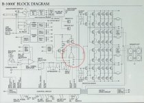
As far as I can see, it does use global NFB, except for the balanced line receiver at the very front. Have a look at the encircled op-amp.
Correct me if I'm wrong.
Cheers,
Edmond.
Terry Demol said:That is extremely linear for an amp that is sans global FB and
uses only some form of EC.
Hi Terry,
How do you know it is "sans global FB".
As far as I can see, it does use global NFB, except for the balanced line receiver at the very front. Have a look at the encircled op-amp.
Correct me if I'm wrong.
Cheers,
Edmond.
Attachments
Re: Re: Re: Re: ODNF
I didn't have a close look at the schematic, just the quote:
"Luxman's patented ODNF circuitry has redefined the relationship
between music signals and noise and does not use phase
compensation or NFB loops in the music signal path, instead it
accurately isolates distortion components to cancel them."
I'll check the schematic more closely.
cheers
T
Edmond Stuart said:
Hi Terry,
How do you know it is "sans global FB".
As far as I can see, it does use global NFB, except for the balanced line receiver at the very front. Have a look at the encircled op-amp.
Correct me if I'm wrong.
Cheers,
Edmond.
I didn't have a close look at the schematic, just the quote:
"Luxman's patented ODNF circuitry has redefined the relationship
between music signals and noise and does not use phase
compensation or NFB loops in the music signal path, instead it
accurately isolates distortion components to cancel them."
I'll check the schematic more closely.
cheers
T
ODNF
Hi Terry,
No NFB loops in the music signal path???
Considering that error FB is just a special form of NFB (with exactly the same limitations!), these guys are clearly talking through their hat.
Cheers,
Edmond
Hi Terry,
No NFB loops in the music signal path???
Considering that error FB is just a special form of NFB (with exactly the same limitations!), these guys are clearly talking through their hat.
Cheers,
Edmond
Re: ODNF
Well, I don't think they were counting on you to buy one of these anyway.. 😉
Jan Didden
Edmond Stuart said:
Hi Glen,
With 70ppm distortion, I wonder if their ODNF circuitry is really worth a patent. Or is it just another marketing trick?
Besides, a claim like this: "This new technology also ensures that need for a DC servo circuit is alleviated, again improving sound quality." makes me even more suspicious.
Cheers,
Edmond.
Well, I don't think they were counting on you to buy one of these anyway.. 😉
Jan Didden
Re: Re: ODNF
Of course, a cynical bastard like me does not belong to their clientele . 😀
BTW, their blah blah on the power cords says enough.
Cheers,
Edmond.
janneman said:Well, I don't think they were counting on you to buy one of these anyway.. 😉
Jan Didden
Of course, a cynical bastard like me does not belong to their clientele . 😀
BTW, their blah blah on the power cords says enough.
Cheers,
Edmond.
Re: Re: EC
Hi Jan,
Using EC around a stage having more than unity gain is well explained in your second Elektor article about the VAS of the PAX. When I went along the text, I made suppositions which were then confirmed by the following parts.
janneman said:
Yes that will certainly work, but it takes that input buffer/ current conveyor outside the ec loop. The nice thing about Forr's idea was that it also corected errors of that input stage.
@ Forr:
You show the amp and summer blocks as unity-gain connected opamps. That is no requirement; one of the nice things of ec (for me 😉 ) is that you can explore low-gain, open loop circuits for the Vas as well as the output stage.
Jan Didden
Hi Jan,
Using EC around a stage having more than unity gain is well explained in your second Elektor article about the VAS of the PAX. When I went along the text, I made suppositions which were then confirmed by the following parts.
Luxman ODNF use a 2nd differential system to compare input and output, and put it as a signal for halfside of VAS.
It resembles fig.2 in this patent 4785257
It resembles fig.2 in this patent 4785257
Another approach would be to reduce the ec conceptual circuit to a single fb loop like countless engineering students have been learning to do for eons.
Say you call the forward gain blok K, and the summer that sums the feedback from the input and the output of K, B. (Let's assume the input summer is exactly 1 just for now).
Then you can move the K-input pick-off to the K-output if you divide the magnitude by K.
You then get a single feedback loop amp with forward gain block K, and feedback of value B(1-1/K). It is then immediately apparent that when K = 1, there is no feedback at all. If K<1, which would normally be the case with an EF output stage, you will get pos feedback, and, of course, you get neg feedback when K>1. And, the feeedback factors are really quite small for realistic K values.
It's nicely illustrated if you plot the feedback vs K as in the graph below. (The RED is with B=1, and the BLUE and YELLOW with B=0.9 and B=1.1 respectively. These outliers are exaggerated for illustrative purposes; a B within 1% of '1' is easily done without adjustments).
So, what you see, and for me was counterintuitive, that even with a K=0.9, the pos feedback is less than a dB.
Jan Didden
Attachments
- Home
- Amplifiers
- Solid State
- Bob Cordell Interview: Error Correction