Edmond Stuart said:PS: How did you measure the tempco of the bias generator? (if you did it at all)
For your use, I didn't measure it.
For others, indirectly. I measured the tempco of the power devices and then biased them at about 50mA, 100mA, 150mA, 200mA, 250mA. For each bias point I started from room temperature and watched the variation of the bias at the final temperature (measured with a LM35 temperature sensor mounted on an adapter, my regular temperature measurement tool). The rest is math.
Unfortunately I have no doubts you did indeed simulate this thing. Care to share the circuit and method are you using?
Edit: temperatures were measured both at the device case (by attaching the temperature sensor fixture to the device) and at the heatsink. Using the Rth values from the data sheets (for the power device and the Berquist SilPads that I am using) the results were consistent.
Hello ,
I am new in this discussion .
In a feedback or feedforward amplifier theses tempco problems seems me a little out . The correction is generally loose , precise correction overemphasise thermal feedback problems like thermal inertia .
Every ones know that tempco of real world power FET's pairs are unpredictable . The best solution is using bias current equal to the zero tempco point . This is not possible with all FET's in B/AB class .
Doubling or halving bias current gives do not double distortion only no bias gives you much higher distortion .
The real problem is avoiding no bias point and avoiding thermal overrun on the bench with real world FET's .
A risky business
The negative tempco region can cause no bias
The positive tempco region can cause thermal overrun
Over corrected tempco can cause both !
regards
HEC bias generator
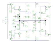
I have used the circuit of Bob's HEC amp (see below). All BJTs are 2SA1407/2SC3601 (your models, btw).
First, I've varied the temperature of all BJTs from 0 to 50 degrees C. This gave a TC between P and Q of -5.55mV/K, less than I expected.
So I also "measured" the Vbe-TC of Q30 and Q31. Together, this was -3.33mV/K (so -1.67mV/K per device), which is also less than the expected -2mV/K. Wrong models?
Next, I varied the temperature of only Q22 and Q23 (keeping the other BJTs at 27 dgr C) and got a TC between P and Q of -6.47mV/K. Apparently, the temperature of the rest of the circuit has also an effect on the bias voltage.
BTW1, the 22V Zener D8 in the original schematic has also a TC, adding one more uncertainty to this bias scheme.
BTW2, you are using lateral MOSFETs in the PGP amp. These devices have a near zero TC at the nominal quiescent current and a negative Id-TC at higher currents. Nevertheless Q22 and Q23 are mounted on the heat sink, resulting in overcompensation. Care to explain?
syn08 said:........
Care to share the circuit and method are you using?
........
I have used the circuit of Bob's HEC amp (see below). All BJTs are 2SA1407/2SC3601 (your models, btw).
First, I've varied the temperature of all BJTs from 0 to 50 degrees C. This gave a TC between P and Q of -5.55mV/K, less than I expected.
So I also "measured" the Vbe-TC of Q30 and Q31. Together, this was -3.33mV/K (so -1.67mV/K per device), which is also less than the expected -2mV/K. Wrong models?
Next, I varied the temperature of only Q22 and Q23 (keeping the other BJTs at 27 dgr C) and got a TC between P and Q of -6.47mV/K. Apparently, the temperature of the rest of the circuit has also an effect on the bias voltage.
BTW1, the 22V Zener D8 in the original schematic has also a TC, adding one more uncertainty to this bias scheme.
BTW2, you are using lateral MOSFETs in the PGP amp. These devices have a near zero TC at the nominal quiescent current and a negative Id-TC at higher currents. Nevertheless Q22 and Q23 are mounted on the heat sink, resulting in overcompensation. Care to explain?
Attachments
Re: HEC bias generator
1. Not necessary wrong models, but the lack of good modelling of the thermal effects in the Spice BJT model template (and the MOSFET model template is even worse!). I know close to nothing to MicroCap, but in other simulators that I have used, there are separate device models for high/low temperatures.
2. I'm pretty sure the rest of the circuit has an impact on the bias as well.
3. You are right. The trannies can, of course, be mounted vertically on the PCB however, for whatever reason, placing them on the HS doesn't impact a iota the laterals bias (at 150mA). Honestly, I haven't cared much to analyze/simulate as of why, but I'm sure there is a good explanation. So I chosed to place them on the HS as an "universal" solution if eventually it is to change the output devices.
You can go ahead and simulate whatever you feel like, but I need (as a former Spice "worker") to warn you and others again: as much as simulations should always be taken with a grain of salt, when it comes to thermal analysis and noise analysis Spice really sucks big times, and there isn't much you can do to fix this, unless you would have fun (for example) including explicit shot noise generators in your schematic. One version of Spice could be better than others, but the results are usually BS anyway.
BTW, I have updated the 2SA1407/2SC3601 models. Make sure you are using these.
http://www.diyaudio.com/forums/showthread.php?postid=1369666#post1369666
Edmond Stuart said:
So I also "measured" the Vbe-TC of Q30 and Q31. Together, this was -3.33mV/K (so -1.67mV/K per device), which is also less than the expected -2mV/K. Wrong models?
Next, I varied the temperature of only Q22 and Q23 (keeping the other BJTs at 27 dgr C) and got a TC between P and Q of -6.47mV/K. Apparently, the temperature of the rest of the circuit has also an effect on the bias voltage.
Nevertheless Q22 and Q23 are mounted on the heat sink, resulting in overcompensation. Care to explain?
1. Not necessary wrong models, but the lack of good modelling of the thermal effects in the Spice BJT model template (and the MOSFET model template is even worse!). I know close to nothing to MicroCap, but in other simulators that I have used, there are separate device models for high/low temperatures.
2. I'm pretty sure the rest of the circuit has an impact on the bias as well.
3. You are right. The trannies can, of course, be mounted vertically on the PCB however, for whatever reason, placing them on the HS doesn't impact a iota the laterals bias (at 150mA). Honestly, I haven't cared much to analyze/simulate as of why, but I'm sure there is a good explanation. So I chosed to place them on the HS as an "universal" solution if eventually it is to change the output devices.
You can go ahead and simulate whatever you feel like, but I need (as a former Spice "worker") to warn you and others again: as much as simulations should always be taken with a grain of salt, when it comes to thermal analysis and noise analysis Spice really sucks big times, and there isn't much you can do to fix this, unless you would have fun (for example) including explicit shot noise generators in your schematic. One version of Spice could be better than others, but the results are usually BS anyway.
BTW, I have updated the 2SA1407/2SC3601 models. Make sure you are using these.
http://www.diyaudio.com/forums/showthread.php?postid=1369666#post1369666
Re: Re: HEC bias generator
It doesn't impact a iota? Come on, are you kidding?
(it's only true if Yfs is zero)
syn08 said:[snip]
3. You are right. The trannies can, of course, be mounted vertically on the PCB however, for whatever reason, placing them on the HS doesn't impact a iota the laterals bias (at 150mA).
[snip]
It doesn't impact a iota?
Come on, are you kidding?(it's only true if Yfs is zero)
Re: Re: Re: HEC bias generator
Iota > 5mA
Edmond Stuart said:
It doesn't impact a iota?
(it's only true if Yfs is zero)
Iota > 5mA
Re: Re: Re: Re: HEC bias generator
True, iota >> 5mA (25mA or so). Anyhow, it's bad practice.
syn08 said:Iota > 5mA
True, iota >> 5mA (25mA or so). Anyhow, it's bad practice.
Re: Re: Re: Re: Re: HEC bias generator
Speak for your simulations only. The bias with the pair on HS after heating up to 70-80C is within a 5mA "iota" to the "cold" value (150mA).
Edmond Stuart said:
True, iota >> 5mA (25mA or so). Anyhow, it's bad practice.
Speak for your simulations only. The bias with the pair on HS after heating up to 70-80C is within a 5mA "iota" to the "cold" value (150mA).
Re: HEC bias generator
Hi Edmond,
I think I see the problem. You are using the Toshiba MOSFETs, which have a much smaller VGSon of only about 2V. I use the HEXFETs, with a VGSon of about 4V. In my circuit, there is a resistor from the base of Q22 to the base of Q23 to cause the bias to spread by the necessary amount. You don't have this resistor because the Toshiba devices don't need as much bias spread. This extra resistor increases the effective amount of Vbe multiplication of the combination of Q22 and Q23.
I have more Vbe multiplication to bias my HEXFETs, so I end up with more temperature slope.
The above, in combination with the lower than expected per-transistor Vbe TC, probably explains the differences.
While I determined empirically that placing only one of the two error amplifier transistors on the heatsink gave good thermal tracking, it could be the case that both of them may need to be on the heatsink if the Toshiba devices are used and they still have 5.5 mV/C TC Vgs, while still having a VGSon that is only about half as much as that of the HEXFETs.
Cheers,
Bob
Edmond Stuart said:
I have used the circuit of Bob's HEC amp (see below). All BJTs are 2SA1407/2SC3601 (your models, btw).
First, I've varied the temperature of all BJTs from 0 to 50 degrees C. This gave a TC between P and Q of -5.55mV/K, less than I expected.
So I also "measured" the Vbe-TC of Q30 and Q31. Together, this was -3.33mV/K (so -1.67mV/K per device), which is also less than the expected -2mV/K. Wrong models?
Next, I varied the temperature of only Q22 and Q23 (keeping the other BJTs at 27 dgr C) and got a TC between P and Q of -6.47mV/K. Apparently, the temperature of the rest of the circuit has also an effect on the bias voltage.
BTW1, the 22V Zener D8 in the original schematic has also a TC, adding one more uncertainty to this bias scheme.
BTW2, you are using lateral MOSFETs in the PGP amp. These devices have a near zero TC at the nominal quiescent current and a negative Id-TC at higher currents. Nevertheless Q22 and Q23 are mounted on the heat sink, resulting in overcompensation. Care to explain?
Hi Edmond,
I think I see the problem. You are using the Toshiba MOSFETs, which have a much smaller VGSon of only about 2V. I use the HEXFETs, with a VGSon of about 4V. In my circuit, there is a resistor from the base of Q22 to the base of Q23 to cause the bias to spread by the necessary amount. You don't have this resistor because the Toshiba devices don't need as much bias spread. This extra resistor increases the effective amount of Vbe multiplication of the combination of Q22 and Q23.
I have more Vbe multiplication to bias my HEXFETs, so I end up with more temperature slope.
The above, in combination with the lower than expected per-transistor Vbe TC, probably explains the differences.
While I determined empirically that placing only one of the two error amplifier transistors on the heatsink gave good thermal tracking, it could be the case that both of them may need to be on the heatsink if the Toshiba devices are used and they still have 5.5 mV/C TC Vgs, while still having a VGSon that is only about half as much as that of the HEXFETs.
Cheers,
Bob
Re: Re: HEC bias generator
I don't think so.
E.G. Stuart hates lateral MOSFETs because good Spice models do not exist. He sees no good reason why one should use these (quote) "slow, low gain, obsolete" devices.
As such, each and every output power stage he is simulating uses 2SK1530/2SJ201. This pair has still less bias spread than your pair of verticals, being in between the Toshiba laterals and your HEXFETs.
Most likely, the Spice thermal simulation results are very poor. It's like hitting nails with a microscope.
Bob Cordell said:
I think I see the problem. You are using the Toshiba MOSFETs, which have a much smaller VGSon of only about 2V.
I don't think so.
E.G. Stuart hates lateral MOSFETs because good Spice models do not exist. He sees no good reason why one should use these (quote) "slow, low gain, obsolete" devices.
As such, each and every output power stage he is simulating uses 2SK1530/2SJ201. This pair has still less bias spread than your pair of verticals, being in between the Toshiba laterals and your HEXFETs.
Most likely, the Spice thermal simulation results are very poor. It's like hitting nails with a microscope.
Re: HEC bias generator
According to your own figures, the TC of the bias generator is 6.9mV/K. If the temperature rises from 25 to 75C, this means a bias voltage drop of 50*6.9mV = 345mV, or per OP device 172.5mV. According to the data sheets, this means a decrease of Id from 150mA to about 80mA. As you see, slightly more than 5mA. 😀
syn08 said:Speak for your simulations only. The bias with the pair on HS after heating up to 70-80C is within a 5mA "iota" to the "cold" value (150mA).
According to your own figures, the TC of the bias generator is 6.9mV/K. If the temperature rises from 25 to 75C, this means a bias voltage drop of 50*6.9mV = 345mV, or per OP device 172.5mV. According to the data sheets, this means a decrease of Id from 150mA to about 80mA. As you see, slightly more than 5mA. 😀
Re: Re: Re: HEC bias generator
Actually, I was referring to his schematic, which uses the Toshiba verticals. They are the ones with VGSon of about 2V.
Laterals have a VGSon of about 1V or less.
I know people will throw tomatos at me, but I also prefer vertical MOSFETs to Laterals. It is very true, however, that the zero tempco point of the laterals is very convenient, and that their greater tolerance to abuse is nice.
Cheers,
Bob
syn08 said:
I don't think so.
E.G. Stuart hates lateral MOSFETs because good Spice models do not exist. He sees no good reason why one should use these (quote) "slow, low gain, obsolete" devices.
As such, each and every output power stage he is simulating uses 2SK1530/2SJ201. This pair has still less bias spread than your pair of verticals, being in between the Toshiba laterals and your HEXFETs.
Most likely, the Spice thermal simulation results are very poor. It's like hitting nails with a microscope.
Actually, I was referring to his schematic, which uses the Toshiba verticals. They are the ones with VGSon of about 2V.
Laterals have a VGSon of about 1V or less.
I know people will throw tomatos at me, but I also prefer vertical MOSFETs to Laterals. It is very true, however, that the zero tempco point of the laterals is very convenient, and that their greater tolerance to abuse is nice.
Cheers,
Bob
Re: Re: Re: HEC bias generator
What do you mean by "E.G. Stuart"? Something like "A.H. Cordell, as you call Bob?syn08 said:..........
E.G. Stuart
..............
Re: Re: HEC bias generator
Hi Bob,
Thanks for solving this TC mystery. Indeed, placing a resistor between the basis of Q22 and Q23 does increase the TC of the bias generator to the expected/intended value.
Cheers,
Edmond.
Bob Cordell said:Hi Edmond,
I think I see the problem. You are using the Toshiba MOSFETs, which have a much smaller VGSon of only about 2V. I use the HEXFETs, with a VGSon of about 4V. In my circuit, there is a resistor from the base of Q22 to the base of Q23 to cause the bias to spread by the necessary amount. You don't have this resistor because the Toshiba devices don't need as much bias spread. This extra resistor increases the effective amount of Vbe multiplication of the combination of Q22 and Q23.
I have more Vbe multiplication to bias my HEXFETs, so I end up with more temperature slope.
The above, in combination with the lower than expected per-transistor Vbe TC, probably explains the differences.
While I determined empirically that placing only one of the two error amplifier transistors on the heatsink gave good thermal tracking, it could be the case that both of them may need to be on the heatsink if the Toshiba devices are used and they still have 5.5 mV/C TC Vgs, while still having a VGSon that is only about half as much as that of the HEXFETs.
Cheers,
Bob
Hi Bob,
Thanks for solving this TC mystery. Indeed, placing a resistor between the basis of Q22 and Q23 does increase the TC of the bias generator to the expected/intended value.
Cheers,
Edmond.
Re: Re: HEC bias generator
Huh? You certainly start worrying me, I know you can do better 😀
Post #3317 above, quote:
"PSpice is telling me the total tempco is 6.9mV/C."
How much I trust spice (in particular in such matters) it's already obvious.
Edmond Stuart said:
According to your own figures, the TC of the bias generator is 6.9mV/K.
Huh? You certainly start worrying me, I know you can do better 😀
Post #3317 above, quote:
"PSpice is telling me the total tempco is 6.9mV/C."
How much I trust spice (in particular in such matters) it's already obvious.
KSTR said:
Me 2 😀 😀 😀
Re: Re: Re: HEC bias generator
You too!
Anyhow, I'm through with you, completely!, and I've put you on the ignore list. Bye bye.
syn08 said:Huh? You certainly start worrying me, I know you can do better 😀
................
You too!
Anyhow, I'm through with you, completely!, and I've put you on the ignore list. Bye bye.
Re: Re: Re: Re: HEC bias generator
Thank you very much! I feel honoured in receiving from you (well, almost) the same level of despise as Toshiba laterals, prof. Hawksford and the MIT and Stanford staff that stubbornly keep teaching and preaching knowledge instead of meaningless and unverifiable numbers.
I'll keep an eye on your web site and patiently wait for your experimental results.
Edmond Stuart said:
Anyhow, I'm through with you, completely!, and I've put you on the ignore list.
Thank you very much! I feel honoured in receiving from you (well, almost) the same level of despise as Toshiba laterals, prof. Hawksford and the MIT and Stanford staff that stubbornly keep teaching and preaching knowledge instead of meaningless and unverifiable numbers.
I'll keep an eye on your web site and patiently wait for your experimental results.
- Home
- Amplifiers
- Solid State
- Bob Cordell Interview: Error Correction