Re: Re: Clipping
Hi Bob,
No, it is certainly not a CMCL VAS without a clamp.
It is a simulation of an amp which I found in some old Siliconix handbook. 🙁
Cheers, Edmond.
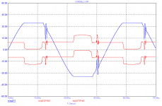
Bob Cordell said:Wow, that's pretty ugly! Is that how the CMCL VAS behaves in clipping if special clipping measures are not taken?
A more conventional input/VAS circuit, even without clipping measures like Baker clamps, does not behave that badly.
Cheers,
Bob
Hi Bob,
No, it is certainly not a CMCL VAS without a clamp.
It is a simulation of an amp which I found in some old Siliconix handbook. 🙁
Cheers, Edmond.
Re: Re: Re: Re: VAS
Edmond,
I read your post carefully and patiently, and responded in that way. Why are you being so grumpy?
You basically just didn't answer the reasonable question I asked.
I have no problem with you disagreeing with my understanding of what the different classes of operation are, but we need to understand if there are differences so we can have an intelligent discussion.
I can only conclude at this point that your VAS is not operating in Class-A (by my definition) when its peak output current exceeds twice its standing current.
Cheers,
Bob
Edmond Stuart said:
Hi Bob,
Indeed, you are missing something. For example. the patience and the willing to read my post more carefully.
I'm not redefining the meaning of class-A, I haven't even used that term.
I only said that "The 'other' VAS is never turned off completely.", and I really don't care how well it fits into some type of class.
Cheers, Edmond.
Edmond,
I read your post carefully and patiently, and responded in that way. Why are you being so grumpy?
You basically just didn't answer the reasonable question I asked.
I have no problem with you disagreeing with my understanding of what the different classes of operation are, but we need to understand if there are differences so we can have an intelligent discussion.
I can only conclude at this point that your VAS is not operating in Class-A (by my definition) when its peak output current exceeds twice its standing current.
Cheers,
Bob
Re: Re: Re: Clipping
Glad to hear it is not a CMCL. I honestly got the impression that you were illustrating the behavior of a CMCL when clipping measures are not taken. It would have been helpful if you told us up front what it was you were illustrating. I'm not a very good mind reader.
Cheers,
Bob
Edmond Stuart said:
Hi Bob,
No, it is certainly not a CMCL VAS without a clamp.
It is a simulation of an amp which I found in some old Siliconix handbook. 🙁
Cheers, Edmond.
Glad to hear it is not a CMCL. I honestly got the impression that you were illustrating the behavior of a CMCL when clipping measures are not taken. It would have been helpful if you told us up front what it was you were illustrating. I'm not a very good mind reader.
Cheers,
Bob
Re: Re: Re: Re: Re: VAS
There ain't no disagreement between us about the different classes.
Bob Cordell said:Edmond,
I read your post carefully and patiently, and responded in that way. Why are you being so grumpy?
You basically just didn't answer the reasonable question I asked.
I have no problem with you disagreeing with my understanding of what the different classes of operation are, but we need to understand if there are differences so we can have an intelligent discussion.
I can only conclude at this point that your VAS is not operating in Class-A (by my definition) when its peak output current exceeds twice its standing current.
Cheers,
Bob
There ain't no disagreement between us about the different classes.
Re: Re: Re: Re: Clipping
No need to be a good mind reader. Just have a careful look at the graph and reread my previous hint. Then you will soon discover who's amplifier behaves so well. 🙄
Cheers, Edmond.
Bob Cordell said:Glad to hear it is not a CMCL. I honestly got the impression that you were illustrating the behavior of a CMCL when clipping measures are not taken. It would have been helpful if you told us up front what it was you were illustrating. I'm not a very good mind reader.
Cheers,
Bob
No need to be a good mind reader. Just have a careful look at the graph and reread my previous hint. Then you will soon discover who's amplifier behaves so well. 🙄
Cheers, Edmond.
Re: Re: Re: Re: Re: Re: VAS
Edmond,
You still didn't answer the reasonable questions i posed. This silly game playing of yours doesn't benefit anybody's understanding.
Bob
Edmond Stuart said:
There ain't no disagreement between us about the different classes.
Edmond,
You still didn't answer the reasonable questions i posed. This silly game playing of yours doesn't benefit anybody's understanding.
Bob
An Inconvenient Truth
Hi Bob,
Apparently my "silly game playing" is too difficult for you.
I told you that the amp was form an old Siliconix handbook, more precisely, Mospower Applications Handbook, chapter 6, pp. 111-124. What else did you expect?
As the clipping behavior is rather embarrassing, I also masked (more or less) the caption of the graph, but, regrettably, you didn't grab it.
Therefore you oblige me to make clear in less covert terms that it is your amp that behaves so badly when a couple of variables deviate a little bit from their nominal values, that is, all in the same wrong direction. To name a few:
1. The supply voltage of the front end.
2. The supply voltage of the output stage.
3. The threshold voltage of the MOSFETs (2...4V)
4. The Zener voltage of D8 (22V)
5. The Zener voltages of D9 and D10 (4.7V)
A simple Baker clamp around the VAS is far from optimal, in particular when the front end and the output stage are fed by different PSUs.
A better approach is to make use of a clamping circuit that 'looks' where and why it really goes wrong: saturation of the (pre) drivers. If a driver is almost running out of steam (Vce<0.4V), my clamping circuit sends a signal back to the feedback node of the input stage, preventing saturation not only of the output stage but of all other stages as well.
Also this clamp works independently of supply voltages and is insensitive to zeners, threshold voltages, etc.
Cheers, Edmond.
Cheers, Edmond.
Bob Cordell said:Edmond,
You still didn't answer the reasonable questions i posed. This silly game playing of yours doesn't benefit anybody's understanding.
Bob
Hi Bob,
Apparently my "silly game playing" is too difficult for you.
I told you that the amp was form an old Siliconix handbook, more precisely, Mospower Applications Handbook, chapter 6, pp. 111-124. What else did you expect?
As the clipping behavior is rather embarrassing, I also masked (more or less) the caption of the graph, but, regrettably, you didn't grab it.
Therefore you oblige me to make clear in less covert terms that it is your amp that behaves so badly when a couple of variables deviate a little bit from their nominal values, that is, all in the same wrong direction. To name a few:
1. The supply voltage of the front end.
2. The supply voltage of the output stage.
3. The threshold voltage of the MOSFETs (2...4V)
4. The Zener voltage of D8 (22V)
5. The Zener voltages of D9 and D10 (4.7V)
A simple Baker clamp around the VAS is far from optimal, in particular when the front end and the output stage are fed by different PSUs.
A better approach is to make use of a clamping circuit that 'looks' where and why it really goes wrong: saturation of the (pre) drivers. If a driver is almost running out of steam (Vce<0.4V), my clamping circuit sends a signal back to the feedback node of the input stage, preventing saturation not only of the output stage but of all other stages as well.
Also this clamp works independently of supply voltages and is insensitive to zeners, threshold voltages, etc.
Cheers, Edmond.
Cheers, Edmond.
Attachments
You tell them, Edmond! Old guys should stick together. I haven't followed EVERY response on this thread, but I recognize the TONE! BTW I just renewed my IEEE 'Life' membership to continue for a total of 44 years. People should respect experience, rather than belittle it. I will be 66 this month.
PS Don't answer questions that are really a 'trap'. It is not worth your time and trouble. 😉
PS Don't answer questions that are really a 'trap'. It is not worth your time and trouble. 😉
john curl said:You tell them, Edmond! Old guys should stick together. I haven't followed EVERY response on this thread, but I recognize the TONE! BTW I just renewed my IEEE 'Life' membership to continue for a total of 44 years. People should respect experience, rather than belittle it. I will be 66 this month.
PS Don't answer questions that are really a 'trap'. It is not worth your time and trouble. 😉
Hi John,
Old geezers will never die. 😀
It's 52 years ago now, when a built my first transistorized amplifier!
Cheers, Edmond.
PS: Thanks for your advice!
Edmond, you started in solid state electronics, years before I did. At that time, I was into tubes, only.
off topic
Hi John,
Actually, I started 57 years ago with "solid state electronics": a crystal receiver. 😀
A few years later, I built a battery operated receiver with tubes. Yes batteries, because my mother forbade to play with the mains voltage (in Europe 220V!).
Another few years later, I got a (valuable!) Christmas present from an uncle (by then one of the directors of the Philips company): a box full of trannies: OC44, OC45, OC71 and OC72, right from the laboratory. That's why I started so early with semi conductors.
Cheers, Edmond.
john curl said:Edmond, you started in solid state electronics, years before I did. At that time, I was into tubes, only.
Hi John,
Actually, I started 57 years ago with "solid state electronics": a crystal receiver. 😀
A few years later, I built a battery operated receiver with tubes. Yes batteries, because my mother forbade to play with the mains voltage (in Europe 220V!).
Another few years later, I got a (valuable!) Christmas present from an uncle (by then one of the directors of the Philips company): a box full of trannies: OC44, OC45, OC71 and OC72, right from the laboratory. That's why I started so early with semi conductors.
Cheers, Edmond.
Re: An Inconvenient Truth
Hi Edmond,
Sorry to be so slow on the uptake. I'll look into it and reply. Right now my day job has me out in San Francisco at the International Solid State Circuits Conference. I've had trouble getting onto the internet until now, and the conference is keeping me extremely busy.
Anyway, I'll look into it and get back to you. I do like Baker Clamps and do agree that there are better and worse ways to do them, including ones that adapt properly. There are a lot of complexities that go into an amplifier from just designing a really low distortion one to designing one that behaves well under all conditions in the real world. That paper was not intended to include all of those niceties; note that it did not even include any addressing of the issues of protection circuits, for example.
Cheers,
Bob
Edmond Stuart said:
Hi Bob,
Apparently my "silly game playing" is too difficult for you.
I told you that the amp was form an old Siliconix handbook, more precisely, Mospower Applications Handbook, chapter 6, pp. 111-124. What else did you expect?
As the clipping behavior is rather embarrassing, I also masked (more or less) the caption of the graph, but, regrettably, you didn't grab it.
Therefore you oblige me to make clear in less covert terms that it is your amp that behaves so badly when a couple of variables deviate a little bit from their nominal values, that is, all in the same wrong direction. To name a few:
1. The supply voltage of the front end.
2. The supply voltage of the output stage.
3. The threshold voltage of the MOSFETs (2...4V)
4. The Zener voltage of D8 (22V)
5. The Zener voltages of D9 and D10 (4.7V)
A simple Baker clamp around the VAS is far from optimal, in particular when the front end and the output stage are fed by different PSUs.
A better approach is to make use of a clamping circuit that 'looks' where and why it really goes wrong: saturation of the (pre) drivers. If a driver is almost running out of steam (Vce<0.4V), my clamping circuit sends a signal back to the feedback node of the input stage, preventing saturation not only of the output stage but of all other stages as well.
Also this clamp works independently of supply voltages and is insensitive to zeners, threshold voltages, etc.
Cheers, Edmond.
Cheers, Edmond.
Hi Edmond,
Sorry to be so slow on the uptake. I'll look into it and reply. Right now my day job has me out in San Francisco at the International Solid State Circuits Conference. I've had trouble getting onto the internet until now, and the conference is keeping me extremely busy.
Anyway, I'll look into it and get back to you. I do like Baker Clamps and do agree that there are better and worse ways to do them, including ones that adapt properly. There are a lot of complexities that go into an amplifier from just designing a really low distortion one to designing one that behaves well under all conditions in the real world. That paper was not intended to include all of those niceties; note that it did not even include any addressing of the issues of protection circuits, for example.
Cheers,
Bob
john curl said:You tell them, Edmond! Old guys should stick together. I haven't followed EVERY response on this thread, but I recognize the TONE! BTW I just renewed my IEEE 'Life' membership to continue for a total of 44 years. People should respect experience, rather than belittle it. I will be 66 this month.
PS Don't answer questions that are really a 'trap'. It is not worth your time and trouble. 😉
Hey! I'm an old guy as well! 🙂.
I swear I was not trying to set a trap for Edmond.
Cheers,
Bob

Re: VAS buffer
Hello Guys,
A question for you. I understand the premise of the point being made regarding the VAS Zout to driver Zin etc at diff frequency's and distortion etc.
My question is though regarding the CCS load for the VAS whether done like Self's (darlington +miller) or a cascode.
Does having a higher CCS load Zout for the VAS arrangement make THD worse with and without miller comp. ?
Or put even more demands on the buffer for lower THD (ie. Higher Zin buffer) ? or is it entirely to do with VAS Zout to buffer Zin?
Sorry for the novice questions.
Thanks
Kevin
PS. I ain't interested in the stability issues etc concerned with different VAS load arrangements.
Edmond Stuart said:
Hi Dimtri,
I'm afraid that Douglas Self will disagree with your figures.
His 'load invariant' amp for example (EW, Jan.1997, pp. 16-24) distorts only -100dB. Above 2kHz it rises steadily to -88dB at 20kHz.
I guess that your figures are based on a rather lame VAS, ie comprising only one tranny. In that case the output impedance of the VAS is much higher and of course, a buffer will have a greater impact.
There are lots of different VASses around here, with OP impedances varying from 25 Ohm to several KOhms at 20kHz. It is this impedance that greatly determines how far a VAS buffer is beneficial. Obviously, with zero impedance, a buffer does nothing.
Therefore, this whole discussion on the blessings of a VAS buffer is pointless without an accurate description of the VAS or at least a mention of its output impedance.
Cheers, Edmond.
Hello Guys,
A question for you. I understand the premise of the point being made regarding the VAS Zout to driver Zin etc at diff frequency's and distortion etc.
My question is though regarding the CCS load for the VAS whether done like Self's (darlington +miller) or a cascode.
Does having a higher CCS load Zout for the VAS arrangement make THD worse with and without miller comp. ?
Or put even more demands on the buffer for lower THD (ie. Higher Zin buffer) ? or is it entirely to do with VAS Zout to buffer Zin?
Sorry for the novice questions.
Thanks
Kevin
PS. I ain't interested in the stability issues etc concerned with different VAS load arrangements.
Re: Re: VAS buffer
Hi Kevin,
First, it looks like you are talking about the case of a single-ended CE VAS stage loaded by a current source, as shown in many of Self's designs. In general, having a higher natural impedance at that node (before considering the feedback effect of Miller compensation) is a good thing. This is because what keeps the natural impedance of that node from being infinity is largely the result of non-linear Early effects in the VAS and current source transistors. That is why cascoding the VAS transistor and the current source is a good thing.
It is also true that, if you are counting the load of the output stage in determining that load impedance, it is good for that load to be a very high impedance as well, since it may also be fairly non-linear. That is why an output triple (the Lochanthi T circuit) is a good thing.
When in some designs VAS load resistors to ground are put in place, they will lower that impedance, but at least those load resistors will be reasonably linear devices. Their net effect will be to make the VAS work a little bit harder to produce the voltage swing, so that may increase distortion a little bit.
Now to the point where we add in the Miller compensating capacitor, usually from the output node of the VAS to its input base, or to the base of the emitter follower driving the VAS transistor. This capacitor creates shunt feedback, and lowers the effective output impedance of the VAS. This is a GOOD thing, because it makes the VAS less affected by nonlinearities of the output stage load.
As frequency goes to a high value, the shunt feedback effect of the Miller capacitor ultimately lowers the output impedance of the VAS to a value that is on the order of 1/gm of the VAS stage, since 100% of what goes into the capacitor winds up at the VAS input.
At lower frequencies, what goes into the Miller capacitor from the VAS output node will see a voltage divider effect against the other impedances present to ground at the base input of the VAS (or at the base of the emitter follower driving the VAS transistor). If those other impedances at the input to the VAS are fairly high (as with a VAS fed by a current mirror and buffered by an emitter follower), then the amount of signal fed back through the Miller capacitor will stay high down to lower frequencies, thus keeping the output impedance of the VAS low down to a lower frequency.
I hope I have been able to answer your question.
Most of what I've said here also applies to push-pull VAS designs, where the current source is replaced by a complementary driven VAS transistor.
Cheers,
Bob
Fanuc said:
Hello Guys,
A question for you. I understand the premise of the point being made regarding the VAS Zout to driver Zin etc at diff frequency's and distortion etc.
My question is though regarding the CCS load for the VAS whether done like Self's (darlington +miller) or a cascode.
Does having a higher CCS load Zout for the VAS arrangement make THD worse with and without miller comp. ?
Or put even more demands on the buffer for lower THD (ie. Higher Zin buffer) ? or is it entirely to do with VAS Zout to buffer Zin?
Sorry for the novice questions.
Thanks
Kevin
PS. I ain't interested in the stability issues etc concerned with different VAS load arrangements.
Hi Kevin,
First, it looks like you are talking about the case of a single-ended CE VAS stage loaded by a current source, as shown in many of Self's designs. In general, having a higher natural impedance at that node (before considering the feedback effect of Miller compensation) is a good thing. This is because what keeps the natural impedance of that node from being infinity is largely the result of non-linear Early effects in the VAS and current source transistors. That is why cascoding the VAS transistor and the current source is a good thing.
It is also true that, if you are counting the load of the output stage in determining that load impedance, it is good for that load to be a very high impedance as well, since it may also be fairly non-linear. That is why an output triple (the Lochanthi T circuit) is a good thing.
When in some designs VAS load resistors to ground are put in place, they will lower that impedance, but at least those load resistors will be reasonably linear devices. Their net effect will be to make the VAS work a little bit harder to produce the voltage swing, so that may increase distortion a little bit.
Now to the point where we add in the Miller compensating capacitor, usually from the output node of the VAS to its input base, or to the base of the emitter follower driving the VAS transistor. This capacitor creates shunt feedback, and lowers the effective output impedance of the VAS. This is a GOOD thing, because it makes the VAS less affected by nonlinearities of the output stage load.
As frequency goes to a high value, the shunt feedback effect of the Miller capacitor ultimately lowers the output impedance of the VAS to a value that is on the order of 1/gm of the VAS stage, since 100% of what goes into the capacitor winds up at the VAS input.
At lower frequencies, what goes into the Miller capacitor from the VAS output node will see a voltage divider effect against the other impedances present to ground at the base input of the VAS (or at the base of the emitter follower driving the VAS transistor). If those other impedances at the input to the VAS are fairly high (as with a VAS fed by a current mirror and buffered by an emitter follower), then the amount of signal fed back through the Miller capacitor will stay high down to lower frequencies, thus keeping the output impedance of the VAS low down to a lower frequency.
I hope I have been able to answer your question.
Most of what I've said here also applies to push-pull VAS designs, where the current source is replaced by a complementary driven VAS transistor.
Cheers,
Bob

Re: No Miller Cap VAS
Hi,
In the arrangement that you have shown, the 1000 pF capacitor and the 330 ohm resistor in series with it cause a pole-zero pair to be formed in the base circuit. The pole looks to be at about 100 kHz and the zero looks to be around 600 kHz. Over this range of frequencies it drops the gain by perhaps 15 dB. Depending on what other poles there are in the collector circuit of the VAS, this will be part of establishing an open-loop gain rolloff characteristic that will pass through 0 dB loop gain at a frequency where there is adequate phase margin. The use of this circuit usually causes one to forego the advantages of pole-splitting that occur in a Miller compensation arrangement, but this is partially made up by the introduction of the zero by the 330 ohms resistor.
Hope this helps,
Bob
GEirin said:Hi Mr. Cordell.
In post 3177, you have explaned the Miller cap function in single T Vas. You would try to explaned with RC filter input VAS (No Miller cap)?
Schematic attached bellow.
Thanks.
GEirin.
Hi,
In the arrangement that you have shown, the 1000 pF capacitor and the 330 ohm resistor in series with it cause a pole-zero pair to be formed in the base circuit. The pole looks to be at about 100 kHz and the zero looks to be around 600 kHz. Over this range of frequencies it drops the gain by perhaps 15 dB. Depending on what other poles there are in the collector circuit of the VAS, this will be part of establishing an open-loop gain rolloff characteristic that will pass through 0 dB loop gain at a frequency where there is adequate phase margin. The use of this circuit usually causes one to forego the advantages of pole-splitting that occur in a Miller compensation arrangement, but this is partially made up by the introduction of the zero by the 330 ohms resistor.
Hope this helps,
Bob
- Home
- Amplifiers
- Solid State
- Bob Cordell Interview: Error Correction