format of files?
Hi powerbecker
I can not open your above files in your zip file since I have not the software ( I presume). Can you put a more standard format (gif or jpg)?
thanks
Hi powerbecker
I can not open your above files in your zip file since I have not the software ( I presume). Can you put a more standard format (gif or jpg)?
thanks
These are simulation files in the common SPICE simulator LTSpice, which can be downloaded for free from Linear's website. Posting them this way, anyone can immediately simulate them and test modifications, so this is far more useful than an image schematic.
powerbecker said:With new "experience" I do a test with TOM´s schematic, he use the OPA541 as poweramp.
In the inverting mode one can use the input as a summer, so you need only 2 additional opamps for EC!
Also in this example the improvement is goog :
THD20 drops down from 0.0084% to 0.000082% !
Heinz!
Heinz!,
I haven't looked at your schematics, yet. But it sounds good! And I am happy to hear that you are still delving into it.
I have been playing with opamp/OPA541 EC power amps in LT-Spice, some more, too, and I can verify the low levels of THD that you mentioned (actually, almost as low as you want, if nothing else matters).
One other thing that EC seems to be good for, which might be of interest: I also now have several quite-simple ec poweramp versions that can drive 20vpp squarewaves into > 2.2uF || 8 ohms, with _ZERO_ overshoot and zero oscillation, from a 1vpp input with 2.5 usec risetime. And those amps almost all also have THD-20 in the .000040% to .000250% range, depending on what tradeoffs are made.
My only real "problem", at the moment, with cap-load squarewave response, comes mainly from clipping of the amplified error signal, or clipping at the difference amp, due to limited power supply voltage levels. But I _think_ I should be able to rearrange things so that that's not a problem.
I'm guessing that that problem exists because, lately, I have been playing with amps with a power stage with gain=1, i.e. a "resistive divide-by-10 and then OPA541 with gain=10" as the power stage, and, an opamp with gain=15 right after the input, before the feedback is subtracted, and no other dividers anywhere. That way allows for relatively low gain in the ec error amp, making it easier to get extremely-low THD levels by raising that gain. But maybe I'll have to try it again with the "original" type of configuration, with the divider at the start of the ec loop, i.e. from the output, and the gain in the power stage, or possibly distributed between the power stage and an input stage.
In the meantime, if I ignore that reality and simply raise the supply rail voltages, I can easily drive "any" value of capacitance, with no overshoot and no ripple whatsoever, with pretty-good speed (I haven't tried, yet, to push the slew-rate to extremes. But 4 to 5 usec _total_ transition time, between the -10v and the +10v "flats" of the squarewaves, is relatively easy, with 2.2uF, and even 3.3uF or more.)
And all of that (above) was using "pure" ec, with one ec FB loop and no other NFB loops.
I have used only "real" (i.e. non-ideal) opamp models, and have found that it helps to use very fast ones, in the EC loop at least. One opamp model that seems pretty good to try, and that is included in the standard LT-Spice libraries, is the LT1363/LT1364, which is rated at 1000v/usec. (And it's actually available from distributors. And I even have some on hand, here, too. But it only tolerates +/-18v rails.)
I have also tried using some LP filtering (200 kHz) of the input signal, and even some more LP after it enters the EC section. It seems that putting a bit of LP filtering on the input signal, as it enters the EC section, helps with the "time delay" problem, as well as making it easier to stabilize a very fast (otherwise) ec loop. It is also helpful when sending squarewaves into capacitive loads, with limited Vsupply rails, since it tends to keep the voltage excursions smaller.
I have also had some pretty-good results, in certain cases, by creating "better high-frequency paths" around the ec loop, by paralleling some of the signal-path resistors with small capacitances (Or I guess I might also be creating some amount of differentiation, sometimes, or just classical-control-theory types of compensations.).
With the topology I've been playing with most recently, at least, stability and performance seem to be able to be pushed pretty far, by making the ec loop, and the output-minus-input difference amp, absolutely as fast as possible, and then using a small (but maybe slightly larger than would otherwise be normal) local feedback capacitance on the input-minus-feedback difference amp. (I kept finding myself needing to do the opposite of what I thought, i.e. when there were high-frequency oscillations/instability in the ec loop, I tended to think that I needed to lower the bandwidth, somewhere, when, in fact, the opposite was almost always true.)
I'll try to post an example circuit, when I get one that is presentable-enough. And I'll take a look at the ones you posted. Thanks!
- Tom Gootee
powerbecker said:With new "experience" I do a test with TOM´s schematic, he use the OPA541 as poweramp.
In the inverting mode one can use the input as a summer, so you need only 2 additional opamps for EC!
Also in this example the improvement is goog :
THD20 drops down from 0.0084% to 0.000082% !
Heinz!
Heinz!,
OK! I ran your OPA541 circuit simulation. Wow! The squarewaves with 1uF and 2.2uF look great!
You can forget about most of what I said, in my last post!
By the way, I noticed that when trying to use the LT1363 in place of the LT1122 opamps, I had to change Gmin to 1e-14, which might be helpful if anyone else ever wants to try the LT1363, with it.
Thanks!
- Tom Gootee
powerbecker said:With new "experience" I do a test with TOM´s schematic, he use the OPA541 as poweramp.
In the inverting mode one can use the input as a summer, so you need only 2 additional opamps for EC!
Also in this example the improvement is goog :
THD20 drops down from 0.0084% to 0.000082% !
Heinz!
Heinz!,
You also solved the problem that I had with the supply rails limiting the value of the capacitance that could be handled in parallel with the load, because of overshoot and clipping of the error feedback or its sum. I don't know why I didn't think of it before, or notice it in your previous schematic and try it! But, your inner feedback loop, from the output of the error amp to the neg input of the output-minus-input difference amp, has dramatically improved the handling of the problem! It also greatly improves the transient response, as well as stability. Thanks again!
- Tom Gootee
Hawksford Error Correction with OpAmp
Regarding the proposal to develop an Error Correction IC:
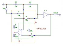
I don't think that this is necessary. Just find a good high speed opamp and use it like in the attached schematic. I have built it with an AD8610 and it works fine without any adjustment, using 1% resistors. CA and CB are needed for stability. You can chose other resistor values; as long as Y/X=D/A=C/B, both voltage error (including DC offset) and nonlinear input current of the buffer stage are corrected, as described by Hawksford. The opamp supply is taken from the buffer's supply lines after bootstrapping to the output and limiting to +-12V.
You must drive this circuit with a low impedance , e.g. a VAS with its own NFB loop.
And my take on the fierce debate whether EC is NFB: Whoever has developed his own EC circuit (there are many ways to do it, always using positive feedback in some way) and turned the magic nulling knob (in reality or in a simulation), knows what it is.
Cheers,
Gerhard
Regarding the proposal to develop an Error Correction IC:
I don't think that this is necessary. Just find a good high speed opamp and use it like in the attached schematic. I have built it with an AD8610 and it works fine without any adjustment, using 1% resistors. CA and CB are needed for stability. You can chose other resistor values; as long as Y/X=D/A=C/B, both voltage error (including DC offset) and nonlinear input current of the buffer stage are corrected, as described by Hawksford. The opamp supply is taken from the buffer's supply lines after bootstrapping to the output and limiting to +-12V.
You must drive this circuit with a low impedance , e.g. a VAS with its own NFB loop.
And my take on the fierce debate whether EC is NFB: Whoever has developed his own EC circuit (there are many ways to do it, always using positive feedback in some way) and turned the magic nulling knob (in reality or in a simulation), knows what it is.
Cheers,
Gerhard
Attachments
I have to say I'm really impressed by what you guys are doing with the EC analyses.
I'd like to re-emphasize my assertion that we should not get too hung up on whether EC is NFB, or not NFB, or a very special form of NFB. And we should also not get too hung up on the exact characterizations that Hawksford or Vanderkuy/Lipshitz have used to describe it.
As I've stated before, it is perfectly reasonable to view EC as NFB with an infinite-gain PFB inside it. It is just as reasonable to characterize the process as error correction based on the way it behaves in practice. Hawksford is a very etherial guy. He may be right in priciple that full-bandwidth EC is impossible without feedforward, but this is only an academic view of very little use. In practice, feedforward EC is just as flawed with practical realities, and achieveing full broadband error correction with feedforward is just as difficult, if not more so, in reality with practical components, as the kind of EC we are discussing here. That is probably why you see virtually no feedforward-based power amps. The Quad current-dumping amp is one of the few that I know of, and it did not even come close to achieving the linearity of the EC we are discussing here.
I personally don't care what you call it, the results are what count.
Keep up the good work, but also maintain a healthy degree of skepticism regarding the realities of SPICE that in some cases might lead to over-optimistic results.
Bob
Re: Hawksford Error Correction with OpAmp
Gerhard:
I beg to disagree. Not that it cannot be done, I simulated and built an EC amplifier based on an OpAmp front end 2 years back with excellent results. The catch is results as per simulations at least are not better in an EC configuration than in a GNF configuration where the loop is closed including the power stage. This is basically no surprise and I bu¡lt the amplifier specifically whith the purpose of testing EC.
The only point to check is whether stability can be tamed the same way as with EC - which I did in hardware - in the case of normal GNF. This I have not verified in practice.
But a discrete or special purpose front end processor may conceivably perform even better, provided its design focuses on inherent linearity and large bandwidth. This remains to be developed and tested.
Rodolfo
gwolf said:Regarding the proposal to develop an Error Correction IC:
I don't think that this is necessary. Just find a good high speed opamp and use it like in the attached schematic. .....
Gerhard:
I beg to disagree. Not that it cannot be done, I simulated and built an EC amplifier based on an OpAmp front end 2 years back with excellent results. The catch is results as per simulations at least are not better in an EC configuration than in a GNF configuration where the loop is closed including the power stage. This is basically no surprise and I bu¡lt the amplifier specifically whith the purpose of testing EC.
The only point to check is whether stability can be tamed the same way as with EC - which I did in hardware - in the case of normal GNF. This I have not verified in practice.
But a discrete or special purpose front end processor may conceivably perform even better, provided its design focuses on inherent linearity and large bandwidth. This remains to be developed and tested.
Rodolfo
EC problems.
From prototypes i have found that the overload characteristics (when EC loop current falls to zero due to excessive error) of all the discrete circuits examined here, including Hawksford's, are truly terrible!
A case of the proverbial cure being worse than the disease!
The remedy, it would appear, is to make the output stage as linear as possible, with the most adverse specified load, before wrapping it in an EC loop.
Rodolfo,
with what exactly do you disagree?
Maybe you misinterpreted my message. I was not talking about an opamp front end, but about using an opamp for implementing Hawksford stile error correction. My front end is a standard VAS with JFET differential input and its own NFB loop. By using a very linear NMOS output stage with high local NFB and the addition of EC the distortion is very low (even THD20).
But you may be right: I am not convinced that EC is the easiest way for getting ultra-low distortion (if this is needed at all).
Cheers,
Gerhard
gwolf said:Rodolfo,
with what exactly do you disagree?
..... I was not talking about an opamp front end, but about using an opamp for implementing Hawksford stile error correction. .....
Gerhard,
Even if you use and OpAmp for the EC loop only, the result is essentially the same as that having the OpAmp with no feedback (i.e. providing its raw OL gain) somewhere along the negative feedback loop. That being the case, there is basically no advantage except for - and this I don't know and have not tested - stabilization issues.
The real difference lies in the alternate approach with an error correction engine specifically designed for the task. So there is where I disagreeded with you, when you said no special discrete or integrated circuit was required.
Let me stress again that I did build prototype and preproduction modules using and OpAmp as EC engine and that it works very well, only it does not fully exploit the possibilities afforded by the topology.
Rodolfo
Re: EC problems.
Clipping behavior is always important, and usually depends on many circuit details. It is especially important to avoid "sticking" or any kind of oscillation during a clipping episode. This is true of both EC circuits and non-EC circuits.
Moreover, it is usually the case that slower circuits being the ones to clip or staurate is a worse situation than with faster ones. Clearly, absent a pre-NFB-loop soft clip circuit (which I advocate), the amplifier has to clip SOMEWHERE if it is going to clip. Often, we have some control over where that will be, and we can also usually prevent any transistors from saturating when they DO clip. If possible, it is best to make the clipping happen before the output stage, whether the circuit uses EC or not.
Some kinds of Baker clamp circuits will allow you to do this. Clipping in the current domain is harder to prevent in the output stage (this includes current limiting), but this probably happens less often unless the speaker load is really bad. This will almost never happen with well-designed high-current amplifiers.
Bob
mikeks said:From prototypes i have found that the overload characteristics (when EC loop current falls to zero due to excessive error) of all the discrete circuits examined here, including Hawksford's, are truly terrible!
A case of the proverbial cure being worse than the disease!
The remedy, it would appear, is to make the output stage as linear as possible, with the most adverse specified load, before wrapping it in an EC loop.
Clipping behavior is always important, and usually depends on many circuit details. It is especially important to avoid "sticking" or any kind of oscillation during a clipping episode. This is true of both EC circuits and non-EC circuits.
Moreover, it is usually the case that slower circuits being the ones to clip or staurate is a worse situation than with faster ones. Clearly, absent a pre-NFB-loop soft clip circuit (which I advocate), the amplifier has to clip SOMEWHERE if it is going to clip. Often, we have some control over where that will be, and we can also usually prevent any transistors from saturating when they DO clip. If possible, it is best to make the clipping happen before the output stage, whether the circuit uses EC or not.
Some kinds of Baker clamp circuits will allow you to do this. Clipping in the current domain is harder to prevent in the output stage (this includes current limiting), but this probably happens less often unless the speaker load is really bad. This will almost never happen with well-designed high-current amplifiers.
Bob
Of significance, Bob, were you able to avoid current-clip in the EC loop of your design while driving 1-2 ohm loads?
Controlled clipping of EC amplifiers
Hi Bob,
While we're on the subject of clipping, I have a quick question.
With an EC amp, it seems advantageous to have a regulated, boosted supply for the input stage, VAS and drivers while running only the output stage from the unregulated supply. It would be good to always have the highest clipping voltage possible without overdriving the output stage (possible when the earlier stages run off a boosted voltage). This seems to imply that the reference voltage for the Baker clamp used by the VAS should track variations in the unregulated supply.
I have heard that your "Klever Klipper" input clipper for gainclones has a clipping level that tracks the unregulated supply, yet suppresses the modulation of the clipping level by the power supply ripple. This seems to imply a low-pass filter between the unregulated supply rails and reference voltage for the clipper.
So my question is, "What is the time constant (if any) of the filter that tracks the PSU variations to establish the clipping level of the Klever Klipper?".
Bob Cordell said:(...) we can also usually prevent any transistors from saturating when they DO clip. (...)
Some kinds of Baker clamp circuits will allow you to do this.
Hi Bob,
While we're on the subject of clipping, I have a quick question.
With an EC amp, it seems advantageous to have a regulated, boosted supply for the input stage, VAS and drivers while running only the output stage from the unregulated supply. It would be good to always have the highest clipping voltage possible without overdriving the output stage (possible when the earlier stages run off a boosted voltage). This seems to imply that the reference voltage for the Baker clamp used by the VAS should track variations in the unregulated supply.
I have heard that your "Klever Klipper" input clipper for gainclones has a clipping level that tracks the unregulated supply, yet suppresses the modulation of the clipping level by the power supply ripple. This seems to imply a low-pass filter between the unregulated supply rails and reference voltage for the clipper.
So my question is, "What is the time constant (if any) of the filter that tracks the PSU variations to establish the clipping level of the Klever Klipper?".
Re: EC problems.
Can you explain nearer what you mean with "overload characteristics.......are truly terrible!"?
I suppose the fairly long recovery time?
What recovery time should be "allowed"?
Also there is no difference to a amp. which use heavy NFB....and in both cases its useful to add clamps...as Bob already says.
Look what happen during voltage overload if you reduce R15 in my example to 1E.
This a simple clamp only for the EC stage. With a clamp inside the "Audioamp" things even will get better.
When I design a amp. I always try to make all stages as linear as for me possible....before I apply NFB and perhaps also EC.
So my view is that EC can be a "remedy" !
Heinz!
mikeks said:From prototypes i have found that the overload characteristics (when EC loop current falls to zero due to excessive error) of all the discrete circuits examined here, including Hawksford's, are truly terrible!
A case of the proverbial cure being worse than the disease!
The remedy, it would appear, is to make the output stage as linear as possible, with the most adverse specified load, before wrapping it in an EC loop.
Can you explain nearer what you mean with "overload characteristics.......are truly terrible!"?
I suppose the fairly long recovery time?
What recovery time should be "allowed"?
Also there is no difference to a amp. which use heavy NFB....and in both cases its useful to add clamps...as Bob already says.
Look what happen during voltage overload if you reduce R15 in my example to 1E.
This a simple clamp only for the EC stage. With a clamp inside the "Audioamp" things even will get better.
When I design a amp. I always try to make all stages as linear as for me possible....before I apply NFB and perhaps also EC.
So my view is that EC can be a "remedy" !
Heinz!
Attachments
mikeks said:Continuing from here.
I would be pleasantly surprised if someone came up with an EC loop (with realistic quiescent currents) that didn't go into current-clip (i.e. complete uselessness) when wrapped around an output stage driving 40V(peak) across 1Ohm.
Also this question I don´t quite understand.
Of course NFB and also EC can and should not try to override a what kind ever used current limiter.
Also in this case the recovery time should be "short"
Heinz!
- Home
- Amplifiers
- Solid State
- Bob Cordell Interview: Error Correction