ingrast said:
Gerhard,
Even if you use and OpAmp for the EC loop only, the result is essentially the same as that having the OpAmp with no feedback (i.e. providing its raw OL gain) somewhere along the negative feedback loop.
Rodolfo,
I still believe this is something totally different. Reducing the discussion to the simple case of voltage error correction, I see the EC amp as a transconductance amplifier with a well defined gain:
- you sense the difference U between buffer input and buffer output
- let the impedance of the buffer input node be R (normaly defined by a resistor in the signal path or by the load resistor of an open loop VAS)
- you add an EC amplifier which injects a current U/R with the correct polarity at the buffer input node
The challenge is the implementation of the EC amplifier. You can use an OTA, a voltage mode opamp, a current mode opamp (the low impedance input being connected to the buffer output) or build your own (which is definitely more fun 🙂.
The EC amplifier must be linear and have a wide bandwidth. It is not yet clear for me whether a simple discrete circuit or an IC is the better way.
Let me stress again that I did build prototype and preproduction modules using and OpAmp as EC engine and that it works very well, only it does not fully exploit the possibilities afforded by the topology.
Can you be more specific on this? What have been the limitations you have met in your implementation (showing the circuit may help)?
Cheers,
Gerhard
gwolf said:
.........
Can you be more specific on this? What have been the limitations you have met in your implementation (showing the circuit may help)?
Cheers,
Gerhard
No matter whether the EC amplifier is voltage, transconductance or any combination, in the end the circuit abstraction boils down to at least a first order network (for the EC amplifier), an inner positive feedback loop and an outer negative feedback loop.
That being the case, and if implemented with an OpAmp, the difference among the plain OpAmp without inner NFB loop or with positive feedback adjusted for cancellation, is the behavior below the dominant pole frequency. For both configurations the slope and 0dB intercept remain unchanged, but for the EC amplifier gain continues to increase to infinity at DC because it behaves in fact as an integrator.
Since what we are seeking is correction margin as the difference between OL gain and working gain, from the above it follows the amount of correction is the same in both cases except as remarked below the OpAmp dominant pole frequency. Since at this frequency the amount of available correction is anyway very high, the return is scant if at all.
Check this post, the EC amplifier (the active part) is represented by S.
Rodolfo
Bob Cordell wrote:
The principal "flaw" or limitation of using FB to reduce errors is the ability to achieve stable loop gain. To eliminate error in theory necessarily implies an unstable system in practice. The limitation of FF for an analogue power amp is that one must have a perfect summing node at the output, one which presents a high Z to the correction amplifier. This is very difficult in an audio power amp because of the very low o/p Z requirement but is used widely in other fields. Even in audio, FF is used in disguise all the time. Balanced circuits do just this - there are two parallel paths where the desired signals are added and the undesired signals are subtracted. John Curl appears to use this technique as a priority over FB techniques. FF does not compromise stability.
FF cancels errors by means of subtraction. FB reduces errors by hunting for a stable equilibrium condition.
Hawksford EC with b=0 (as Bob uses, with an extra FB path) is a FB system. Bob's original circuit applies about 31dB of NFB to the output stage up to about 75kHz (not infinite because this would be impractical) and his real circuit measurements confirm the commensurate reduction in THD.
I agree in the sense that Hawksford's analysis models are not appropriate to be transfered block for block into practical circuits. Even though they are! But I also think understanding the models and what they represent is essential to avoid the pitfalls of doing just that.As I've stated before, it is perfectly reasonable to view EC as NFB with an infinite-gain PFB inside it. It is just as reasonable to characterize the process as error correction based on the way it behaves in practice. Hawksford is a very etherial guy. He may be right in priciple that full-bandwidth EC is impossible without feedforward, but this is only an academic view of very little use.
Of course all practical circuits have limitations but that doesn't mean we should ignore the theory of what we are trying to achieve. A FF system CAN cancel an error in theory whereas a FB cannot cancel an error even in theory. And if you cannot do something in theory you have no chance of doing it in practice.In practice, feedforward EC is just as flawed with practical realities, and achieveing full broadband error correction with feedforward is just as difficult, if not more so, in reality with practical components, as the kind of EC we are discussing here. That is probably why you see virtually no feedforward-based power amps. The Quad current-dumping amp is one of the few that I know of, and it did not even come close to achieving the linearity of the EC we are discussing here.
The principal "flaw" or limitation of using FB to reduce errors is the ability to achieve stable loop gain. To eliminate error in theory necessarily implies an unstable system in practice. The limitation of FF for an analogue power amp is that one must have a perfect summing node at the output, one which presents a high Z to the correction amplifier. This is very difficult in an audio power amp because of the very low o/p Z requirement but is used widely in other fields. Even in audio, FF is used in disguise all the time. Balanced circuits do just this - there are two parallel paths where the desired signals are added and the undesired signals are subtracted. John Curl appears to use this technique as a priority over FB techniques. FF does not compromise stability.
FF cancels errors by means of subtraction. FB reduces errors by hunting for a stable equilibrium condition.
Hawksford EC with b=0 (as Bob uses, with an extra FB path) is a FB system. Bob's original circuit applies about 31dB of NFB to the output stage up to about 75kHz (not infinite because this would be impractical) and his real circuit measurements confirm the commensurate reduction in THD.
Always.I personally don't care what you call it, the results are what count.
Re: Re: EC problems.
I mean overload in the EC loop provoked by excessive error generated by the output stage, as might occur when driving heavy loads (e.g.2Ohms).
In these circumstances the EC loop's transistors are driven alternately into saturation and cut off.
powerbecker said:
Can you explain nearer what you mean with "overload characteristics.......are truly terrible!"?
Heinz!
I mean overload in the EC loop provoked by excessive error generated by the output stage, as might occur when driving heavy loads (e.g.2Ohms).
In these circumstances the EC loop's transistors are driven alternately into saturation and cut off.
traderbam said:.....a FB cannot cancel an error even in theory.....
Untrue.
Clearly you need to get past the stage where everything must be true because it appears in a paper.
http://www.diyaudio.com/forums/showthread.php?postid=1067653#post1067653
http://www.diyaudio.com/forums/showthread.php?postid=1067674#post1067674
http://www.diyaudio.com/forums/showthread.php?postid=1067692#post1067692
http://www.diyaudio.com/forums/showthread.php?postid=1067767#post1067767
http://www.diyaudio.com/forums/showthread.php?postid=1067776#post1067776
http://www.diyaudio.com/forums/showthread.php?postid=1067513#post1067513
http://www.diyaudio.com/forums/showthread.php?postid=1075380#post1075380
traderbam said:Bob's original circuit applies about 31dB of NFB to the output stage up to about 75kHz.....
No.
http://www.diyaudio.com/forums/showthread.php?postid=1074775#post1074775
ingrast said:
No matter whether the EC amplifier is voltage, transconductance or any combination, in the end the circuit abstraction boils down to at least a first order network (for the EC amplifier), an inner positive feedback loop and an outer negative feedback loop.
...
Check this post, the EC amplifier (the active part) is represented by S.
Rodolfo,
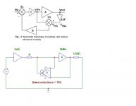
I fear we are not talking about the same subject. In the purest case I am really interested in, there is no outer negative feedback loop and the EC amplifier is B, not S (see the attachment including Fig.3 from your paper).
What is your stability analysis for this case? From simulation and from practise I see that some compensation is needed (reducing the EC efficiency at high frequencies). How is this related to the HF performance of B and A?
Cheers,
Gerhard
Attachments
Gerhard,
Your arrangement is exactly the same as that described by Rodolfo, Yokoyama and this arrangement.
Your arrangement is exactly the same as that described by Rodolfo, Yokoyama and this arrangement.
mikeks said:
Yes, exactly. Therefore I would like to understand the stability issues of it.
After making your VAS with its own NFB as linear as you want, the performance of a power amp without global NFB is limited only by the buffer stage at the end. Make this as linear as you can by applying some local NFB, add EC to it and you have what you want (if your speakers survive it). javascript:smilie('
 ')
')xeye
Cheers,
Gerhard
Originally posted by traderbam
Mikeks responded:Bob's original circuit applies about 31dB of NFB to the output stage up to about 75kHz.....
Mike, go to post #1325. Run the simulation yourself. Then and only then may you contradict me, and only then if you have a rational reason for doing so. Stop being so childish and stop wasting space in this thread and spreading mis-information 😡
Re: Re: Re: EC problems.
Heavy loads were definitely not a problem for my MOSFET power amplifier with error correction. Even though it was only a 50 watt amplifier with a single pair of output transistors, it easily drove 22 amp peaks at 20 kHz into a 1-ohm load. See the tone burst figure in that paper at www.cordellaudio.com.
Bob
mikeks said:
I mean overload in the EC loop provoked by excessive error generated by the output stage, as might occur when driving heavy loads (e.g.2Ohms).
In these circumstances the EC loop's transistors are driven alternately into saturation and cut off.
Heavy loads were definitely not a problem for my MOSFET power amplifier with error correction. Even though it was only a 50 watt amplifier with a single pair of output transistors, it easily drove 22 amp peaks at 20 kHz into a 1-ohm load. See the tone burst figure in that paper at www.cordellaudio.com.
Bob
gwolf said:
..... there is no outer negative feedback loop and the EC amplifier is B, not S .....
What is your stability analysis for this case? ....
Gerhard
Gerhard
In fact there is an outer negative feedback loop from amplifier output through EC amplifier B inverting input to main amplifier input. The positive feedback loop is formed by the B noninverting amplifier input to main amplifier input, and the cancellation condition is as you stated gm=1/R.
Now, it is simpler from the standpoint of stability and performance evaluation, to convert to the equivalent single negative feedback loop configuration, provided you replace B with a convenient first order network model (otherwise you will stumble with a division by 0).
Including the cancellation condition, B and the inner positive feedback loop are replaced with an ideal integrator with the same gain-bandwidth product the original EC amplifier had.
With this in sight, it follows:
1. Stability should in principle not be worst than simply leaving B as an auxiliary inverting loop amplifier (no inner PFB) operating itself open loop (no local NFB). This I have not checked.
2. There is then no particular correction advantage form the EC configuration to the previously indicated single loop NFB.
I reckon that your particular configuration with a transconductance amplifier driving current to the VAS output R probably requires modificatons to convert to the regular single NFB loop, and that in this case it may be advantageous to leave it as is.
Rodolfo
traderbam said:Bob Cordell wrote:I agree in the sense that Hawksford's analysis models are not appropriate to be transfered block for block into practical circuits. Even though they are! But I also think understanding the models and what they represent is essential to avoid the pitfalls of doing just that.
Of course all practical circuits have limitations but that doesn't mean we should ignore the theory of what we are trying to achieve. A FF system CAN cancel an error in theory whereas a FB cannot cancel an error even in theory. And if you cannot do something in theory you have no chance of doing it in practice.
The principal "flaw" or limitation of using FB to reduce errors is the ability to achieve stable loop gain. To eliminate error in theory necessarily implies an unstable system in practice. The limitation of FF for an analogue power amp is that one must have a perfect summing node at the output, one which presents a high Z to the correction amplifier. This is very difficult in an audio power amp because of the very low o/p Z requirement but is used widely in other fields. Even in audio, FF is used in disguise all the time. Balanced circuits do just this - there are two parallel paths where the desired signals are added and the undesired signals are subtracted. John Curl appears to use this technique as a priority over FB techniques. FF does not compromise stability.
FF cancels errors by means of subtraction. FB reduces errors by hunting for a stable equilibrium condition.
Hawksford EC with b=0 (as Bob uses, with an extra FB path) is a FB system. Bob's original circuit applies about 31dB of NFB to the output stage up to about 75kHz (not infinite because this would be impractical) and his real circuit measurements confirm the commensurate reduction in THD.
Always.
You just can't get past this reality that NFB is not perfect. It sounds to me like you should start a thread on practical feedforward error correction amplifiers and see if you can do better than EC with a real feedforward amplifier. No twiddle pots allowed, of course, in the spirit of your earlier posts.
Bob
traderbam said:Originally posted by traderbam
Mikeks responded:
Mike, go to post #1325. Run the simulation yourself. Then and only then may you contradict me, and only then if you have a rational reason for doing so. Stop being so childish and stop wasting space in this thread and spreading mis-information 😡
Your loop-gain sim is incorrect.
Please refer to this post for correct procedure:
http://www.diyaudio.com/forums/showthread.php?postid=1074775#post1074775
Thank you.
Re: Re: Re: Re: EC problems.
Were you able to establish whether or not the error loop's transistors still operated in their linear mode during this process?
What was the THD @20KHz into 1 Ohm?
Bob Cordell said:
Heavy loads were definitely not a problem for my MOSFET power amplifier with error correction. Even though it was only a 50 watt amplifier with a single pair of output transistors, it easily drove 22 amp peaks at 20 kHz into a 1-ohm load. See the tone burst figure in that paper at www.cordellaudio.com.
Bob
Were you able to establish whether or not the error loop's transistors still operated in their linear mode during this process?
What was the THD @20KHz into 1 Ohm?
ingrast said:
Gerhard
In fact there is an outer negative feedback loop from amplifier output through EC amplifier B inverting input to main amplifier input. The positive feedback loop is formed by the B noninverting amplifier input to main amplifier input, and the cancellation condition is as you stated gm=1/R.
...
Thanks, Rodolfo, now things start becoming interesting. I must think about it.
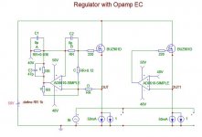
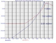
In the meantime I remember a simulation exercise I did some time ago about applying EC to a regulator. Reducing the output impedance of the regulator to near 0 (thats what EC does) should result in a very high load regulation factor. But when I compared this with an active NFB scheme, the results were not so different (see attachments). Reminds me about what you wrote...
Second attachment will follow.
Cheers,
Gerhard
Attachments
mikeks said:I would be pleasantly surprised if someone came up with an EC loop (with realistic quiescent currents) that didn't go into current-clip (i.e. complete uselessness) when wrapped around an output stage driving 40V(peak) across 1Ohm.
Mike,
Some gain compensation could probably go a long way here. If you have a sim of your circuit, have a look at the error correction currents somewhat below current clipping of the EC. If it's the standard EC setup, these currents will look like a low distortion sinusoid at the fundamental frequency. This is just the EC trying to set the gain to exactly 1. The dynamic range of the EC gets eaten up by this useless gain correction.
If you're using the diff amp approach, you can scale one diff amp input with a resistor Rsh as shown in the attachment of this post. In the sim of your circuit using transient with a sine wave and delivering 40A into a 1 Ohm load (with EC disconnected), determine the "gain" Kos of the part of the circuitry being error-corrected. Then determine the resistor Rsh such that the voltage divider ratio has the value Kos. Then scale the diff amp collector resistors up by the reciprocal of Kos to re-establish the cancellation condition. Then the error correction currents should be much smaller in amplitude and look very distorted.
This may overcompensate the 8 Ohm load case though, so you may need to use some intermediate Kos value that splits the error between these two extremes.
In the sim that I've linked above, have a look a the error correction currents in the as-posted condition in transient. Then in the ".param Rsh=" statement, set it to something very large so it's essentially an open circuit. You'll be able to see the benefits of the gain compensation in improving the dynamic range of the EC.
gwolf said:Here is the second part...
Note that this is only AC (small signal) analysis. Large signal behaviour will be affected by non-linearities of opamp and FET, but probably less so in the NFB version.
Gerhard
Mikeks wrote:
What you keep insisting upon is measuring the wrong part of the circuit! You measure the loop including both PFB and NFB circuits. This loop does not exclusively contain the output devices and so doesn't reveal anything useful about the EC feedback correction of the output devices. You have been told this at least 10 times by a number of learned people in this thread. Suck it up and stop criticising without engaging your brain!
I really don't care whether you understand this or anything else. What I do care about is your potential for misleading others in this thread with your insistent erroroneous blather and your "I'm not listening...la, la, la" attitude. Think about others too not just your own ego. Leave it alone!
It most certainly is not. If you are going to criticise then damned well get your facts straight.Your loop-gain sim is incorrect.
What you keep insisting upon is measuring the wrong part of the circuit! You measure the loop including both PFB and NFB circuits. This loop does not exclusively contain the output devices and so doesn't reveal anything useful about the EC feedback correction of the output devices. You have been told this at least 10 times by a number of learned people in this thread. Suck it up and stop criticising without engaging your brain!
I really don't care whether you understand this or anything else. What I do care about is your potential for misleading others in this thread with your insistent erroroneous blather and your "I'm not listening...la, la, la" attitude. Think about others too not just your own ego. Leave it alone!
- Home
- Amplifiers
- Solid State
- Bob Cordell Interview: Error Correction