Brian, please calm down. Raising one's voice is quite useless as a debating tactic. We're all grown ups here, each being a judge for themselves based on presented arguments and supporting evidence.
Regards,
Milan
Regards,
Milan
Bob Cordell wrote:
Oh, I am a big fan of NFB. I reckon that for a power-efficient amp NFB is the way to go if the associated pitfalls of NFB are mitigated (only some of which have been touched on in this thread). For a THD measurement, NFB is probably the best approach too. But for sound quality...now there's a different kettle of fish...
There's a challenge. I might have to try to team up with John Curl for that thread. 😱 😛You just can't get past this reality that NFB is not perfect. It sounds to me like you should start a thread on practical feedforward error correction amplifiers and see if you can do better than EC with a real feedforward amplifier. No twiddle pots allowed, of course, in the spirit of your earlier posts.
Oh, I am a big fan of NFB. I reckon that for a power-efficient amp NFB is the way to go if the associated pitfalls of NFB are mitigated (only some of which have been touched on in this thread). For a THD measurement, NFB is probably the best approach too. But for sound quality...now there's a different kettle of fish...
gwolf said:Here is the second part, showing the output impedances for the two versions. Up to 100kHz and particularly at low frequencies the EC version has clear advantages, if resistor values are optimised (which may not be so easy in practise).
Gerhard
Up to now we were talking audio amplifiers.
What you have verified here is, if low and very low frequency performance is important like a DC supply, then EC is definitely a better choice given the same devices to work with in either alternative.
Note the departure from slope regular negative feedback mandates, while EC goes on down, as it should be being in fact an integrator in the loop.
Rodolfo
traderbam said:Mikeks wrote:It most certainly is not. If you are going to criticise then damned well get your facts straight.
What you keep insisting upon is measuring the wrong part of the circuit! You measure the loop including both PFB and NFB circuits. This loop does not exclusively contain the output devices and so doesn't reveal anything useful about the EC feedback correction of the output devices. You have been told this at least 10 times by a number of learned people in this thread. Suck it up and stop criticising without engaging your brain!
I really don't care whether you understand this or anything else. What I do care about is your potential for misleading others in this thread with your insistent erroroneous blather and your "I'm not listening...la, la, la" attitude. Think about others too not just your own ego. Leave it alone!
Hi Brian,
As shown here, for the umpteenth time, loop-gain in a multi-loop system can only be determined correctly by selecting a node within the mesh such that with this node disconnected all system loops would be disconnected.
LA LA LA!
Ciao!
traderbam said:What you keep insisting upon is measuring the wrong part of the circuit! You measure the loop including both PFB and NFB circuits. This loop does not exclusively contain the output devices and so doesn't reveal anything useful about the EC feedback correction of the output devices.
Moreover, if it was your intention to determine loop-gain within a minor loop, then you must first disable the major loop while retaining its loading on the minor-loop at issue, which you clearly haven't done.
Therefore, you are exceeding wrong in all conceivable respects.
Re: Re: Re: Re: Re: EC problems.
Mike, these are good questions. I did not confirm by measurement that the EC transistors were not saturated or cut off, but I assume the sinewave might have gotten pretty ungly if they did. Moreover, I know that the headroom in the EC circuits was enough to provide the required gate drive for the MOSFETs to achieve 20+ amps.
I did not measure THD into 1 ohm, as the amplifier was only OK for brief bursts at such high levels into such a low load impedance, given that it had only a single pair of output transistors.
Bob
mikeks said:
Were you able to establish whether or not the error loop's transistors still operated in their linear mode during this process?
What was the THD @20KHz into 1 Ohm?
Mike, these are good questions. I did not confirm by measurement that the EC transistors were not saturated or cut off, but I assume the sinewave might have gotten pretty ungly if they did. Moreover, I know that the headroom in the EC circuits was enough to provide the required gate drive for the MOSFETs to achieve 20+ amps.
I did not measure THD into 1 ohm, as the amplifier was only OK for brief bursts at such high levels into such a low load impedance, given that it had only a single pair of output transistors.
Bob
traderbam said:Bob Cordell wrote:There's a challenge. I might have to try to team up with John Curl for that thread. 😱 😛
Oh, I am a big fan of NFB. I reckon that for a power-efficient amp NFB is the way to go if the associated pitfalls of NFB are mitigated (only some of which have been touched on in this thread). For a THD measurement, NFB is probably the best approach too. But for sound quality...now there's a different kettle of fish...
First of all, I did not write what is quoted above, Brian did.
OK, Brian, looks like you've thrown down the old gauntlet. Perhaps you can elaborate on the "associated pitfalls" of NFB that you are referring to that have not been touched on in this thread. We can't discuss your potentially slanderous remarks concerning NFB unless we know what you are referring to. Go for it. Tell us about that kettle of fish, and let us decide for ourselves what that kettle is full of.
Bob
Re: Controlled clipping of EC amplifiers
Hhmm....no answer..anyway it would be better not to use a deep frequency filter, may be better this?
Heinz!
andy_c said:
Hi Bob,
While we're on the subject of clipping, I have a quick question.
With an EC amp, it seems advantageous to have a regulated, boosted supply for the input stage, VAS and drivers while running only the output stage from the unregulated supply. It would be good to always have the highest clipping voltage possible without overdriving the output stage (possible when the earlier stages run off a boosted voltage). This seems to imply that the reference voltage for the Baker clamp used by the VAS should track variations in the unregulated supply.
I have heard that your "Klever Klipper" input clipper for gainclones has a clipping level that tracks the unregulated supply, yet suppresses the modulation of the clipping level by the power supply ripple. This seems to imply a low-pass filter between the unregulated supply rails and reference voltage for the clipper.
So my question is, "What is the time constant (if any) of the filter that tracks the PSU variations to establish the clipping level of the Klever Klipper?".
Hhmm....no answer..anyway it would be better not to use a deep frequency filter, may be better this?
Heinz!
Attachments
andy_c said:
Mike,
Some gain compensation could probably go a long way here. If you have a sim of your circuit, have a look at the error correction currents somewhat below current clipping of the EC. If it's the standard EC setup, these currents will look like a low distortion sinusoid at the fundamental frequency. This is just the EC trying to set the gain to exactly 1. The dynamic range of the EC gets eaten up by this useless gain correction.
If you're using the diff amp approach, you can scale one diff amp input with a resistor Rsh as shown in the attachment of this post. In the sim of your circuit using transient with a sine wave and delivering 40A into a 1 Ohm load (with EC disconnected), determine the "gain" Kos of the part of the circuitry being error-corrected. Then determine the resistor Rsh such that the voltage divider ratio has the value Kos. Then scale the diff amp collector resistors up by the reciprocal of Kos to re-establish the cancellation condition. Then the error correction currents should be much smaller in amplitude and look very distorted.
This may overcompensate the 8 Ohm load case though, so you may need to use some intermediate Kos value that splits the error between these two extremes.
In the sim that I've linked above, have a look a the error correction currents in the as-posted condition in transient. Then in the ".param Rsh=" statement, set it to something very large so it's essentially an open circuit. You'll be able to see the benefits of the gain compensation in improving the dynamic range of the EC.
Hi Andy,
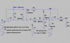
I assume you are referring to attenuation of error before amplification.
I have done just this with the circuit below, as demonstrated here, by attenuating by 1/2 and amplifying by 2.
This prevents the diff. error amps from cutting off when driving 29V across 1Ohm.
Although i increased tail current from 20mA to 30mA, the increase in diff. stage voltage gain still significantly increases non-linearity in the diff. amps.
Attachments
Nevertheless, as indicated here, it would appear impractical to aspire to driving 40V(peak) across 1Ohm without causing the EC loop to go into hard current-clip.
I am now of the view, at least provisionally, that EC loops are best suited to well-defined medium loads, as encountered, for instance, in actively driven 'speaker systems.
I am now of the view, at least provisionally, that EC loops are best suited to well-defined medium loads, as encountered, for instance, in actively driven 'speaker systems.
andy_c said:
Hi Bob,
While we're on the subject of clipping, I have a quick question.
With an EC amp, it seems advantageous to have a regulated, boosted supply for the input stage, VAS and drivers while running only the output stage from the unregulated supply. It would be good to always have the highest clipping voltage possible without overdriving the output stage (possible when the earlier stages run off a boosted voltage). This seems to imply that the reference voltage for the Baker clamp used by the VAS should track variations in the unregulated supply.
I have heard that your "Klever Klipper" input clipper for gainclones has a clipping level that tracks the unregulated supply, yet suppresses the modulation of the clipping level by the power supply ripple. This seems to imply a low-pass filter between the unregulated supply rails and reference voltage for the clipper.
So my question is, "What is the time constant (if any) of the filter that tracks the PSU variations to establish the clipping level of the Klever Klipper?".
Hi Andy, I'm sorry I took so long to get back to you on this.
You are right - the reference voltage for the VAS when using a Baker clamp should track the unregulated supply used to power the output devices. This should be done so that the output devices never clip for lack of supply voltage. This will also keep the VAS out of saturation.
The unregulated supply should be modestly LPF'd before being used as the reference for the Baker clamp, but it need not be a really long time constant, since there is a tradeoff between tracking the supply dips fast enough to keep the output stage out of saturation, and slow enough so as not to modulate the clipping too much by ripple. An LPF that creates about 10-20 dB of attenuation at 120 Hz is probably about right. A second pole is also helpful to keep HF nasties away from the Baker clamp diodes, since they have capacitance. Note that these diodes would like to be rated at at least double the rail voltage and be as low capacitance as possible if a simple conventional Baker clamp is being used.
The "Klever Clipper" works in a similar way, with similar considerations, but it operates at the input of the amplifier, outside the feedback loop. It is a passive-adaptive clipping circuit whose clipping point tracks the unregulated supply. Considerations for filtering the unregulated supply so as to arrive at a reference for the clipper are similar to the ones above. I don't recall the exact time constants I used, but I hope to be able to provide more detailed information on that circuit on my web site soon.
Bob
mikeks said:Nevertheless, as indicated here, it would appear impractical to aspire to driving 40V(peak) across 1Ohm without causing the EC loop to go into hard current-clip.
I am now of the view, at least provisionally, that EC loops are best suited to well-defined medium loads, as encountered, for instance, in actively driven 'speaker systems.
Mike, I must strongly disagree with you. I have lost track of which EC circuit you are talking about, but the one I use has absolutely no problem with headroom driving high current into a load. Keep in mind that if you use an appropriate number of MOSFETs in parallel as dictated by the requirements for the rating of the power amplifier, it does not take very much gate drive beyond the gate drive for quiescent bias to drive the devices to very high currents. Look at the curves.
If you want to drive 40 V peak into 1 ohm, you're talking about an amplifier that is rated at at least 100 watts into 8 ohms. That amplifier will have typically two MOSFET pairs. You are asking for 40 amps on the peaks, so each MOSFET must put out 20 amps. At a quiescent bias of 150 mA, they will already be forward biased by about 4.5V or so. I don't have the curves in front of me, but I think that with an additional forward bias of as little as 2.5V, for a total forward bias of 7V, they will be in the 20 Amp region of operation.
Bob
Bob Cordell said:The unregulated supply should be modestly LPF'd before being used as the reference for the Baker clamp, but it need not be a really long time constant, since there is a tradeoff between tracking the supply dips fast enough to keep the output stage out of saturation, and slow enough so as not to modulate the clipping too much by ripple. An LPF that creates about 10-20 dB of attenuation at 120 Hz is probably about right. A second pole is also helpful to keep HF nasties away from the Baker clamp diodes, since they have capacitance.
Ahh, thanks Bob! I will try that out 🙂.
mikeks said:Nevertheless, as indicated here, it would appear impractical to aspire to driving 40V(peak) across 1Ohm without causing the EC loop to go into hard current-clip.
Mike, your error correction resistors in the collectors of the diff amps are quite low at 100 Ohms. This limits the correction voltage range.
- Home
- Amplifiers
- Solid State
- Bob Cordell Interview: Error Correction