OK thanks.ingrast said:Nixie, could you restate your question?, somehow this has become cluttered and I do not have it clear. See whether I can help a bit.
It is referring to this paper by Hawksford.
I had a discussion with smoking-amp a while back (sorry to bring you in to this dude...) and he was thinking that on stages with gain, one would pasively attenuate the output sample by dividing with the target gain, before subtraction to extract the error; this was in line with what I was thinking. However, in Hawksford's paper, figure 3-1 shows that he multiplies the input sample instead with a reference amplifier, thus adding one more active part to the EC loop. A drawing of the two alternatives is in this attachment. Of course, to subtract one of the signals needs to be inverted, but I assumed an inverting stage since the most common stage with gain is a common source/emitter/cathode configuration (at least in amplifiers I'm interested in). In the Hawksford version a is the inverse of the target gain, whereas in the other it's 1.
Looking at Hawksford's equations in that paper, what I said also gets error null, as I showed in this post.
My question very simply is, is there any downside to doing it the way smoking-amp and I were thinking, by attenuation, instead of adding the amplifier R as Hawksford did.
Nixie said:
...... and he was thinking that on stages with gain, one would pasively attenuate the output sample by dividing with the target gain, before subtraction to extract the error; this was in line with what I was thinking. ...... Of course, to subtract one of the signals needs to be inverted, but I assumed an inverting stage since the most common stage with gain is a common source/emitter/cathode configuration (at least in amplifiers I'm interested in). .....
My question very simply is, is there any downside to doing it the way smoking-amp and I were thinking, by attenuation, instead of adding the amplifier R as Hawksford did.
There are 2 issues here, the passive attenuation for the error correction processing, and the inverting or not nature of the power section to be corrected.
For the first, what I studied and partly shown here (post 795 pag. 80 !!) uses naturally passive attenuation (1/A') for output signal sample. You are right, it is not only perfectly possible, it is sensible.
As for the inverting or not nature of the power section, this is irrelevant as long as the correct additions and substractions are preserved.
My working mesaured prototpypes and preproduction amplifier modules are built that way just fine.
It must be recalled nonetheless that some form of active process is required besides the output stage in order to get anywhere near the "cancellation" condition, and this limits actual performance.
To understand this, one must think feedback error correction under cancellation conditions implies an equivalent loop gain singularity and this cannot be accomplished by purelly passive means.
Rodolfo
Oh, I wasn't disagreeing that another active process is required, just that it seems to me the reference amplifier R in Hawksford's paper yet another active process beyond the necessary.
Hi Nixie,
I've just read that Hawksford paper. It is interesting to me because he basically says that error cancellation is impractical without using feedforward and cites Vanderkooy and Lipshitz! So now we're all agreed.
Regarding your question, I think you are absolutely right. So is Rodolfo. The thing is that Hawksford's paper is quite theoretical and his fig 3.1 is not meant to be an implementation. It is just a diagram for illustrating some points in the text.
Your diagram with the 1/R tem in the output feedback is just as good. You'll also observe that the positive loop in your diagram can be replaced with a forward gain block of 1/(1-a). Then you'll have a conventional NFB diagram.
You see, the "error correction" system is equivalent to a NFB loop as Hawksford illustrates in fig 2.1. The now infamous "null" condition is just the condition when a=1 and the forward gain is infinite...which is not very useful because it is impractical. Hawksford discusses this too.
So the question comes back to what is the most effective practical topology for implementing NFB around an output stage. You have pointed out that blindly mapping fig 3.1 into a schematic may not be.
Brian
So what about the control theory discussion earlier in the thread about NFB being a 1DOF system whereas EC is a 2DOF system? If that is true, it would seem the former is a special case of the latter (fix one of the DOF).Originally posted by traderbam
You see, the "error correction" system is equivalent to a NFB loop
traderbam said:
.......You have pointed out that blindly mapping fig 3.1 into a schematic may not be.
Brian
In fact this is not completely true.
It may be even interesting to consider placing the active part needed for "cancellation" between the main amplifier input and the error extraction node, provided the rest of the error correction front end is kept passive, which in this case can be done.
This gain may be inverting or noninverting, depending on whether the main amplifier is noninverting or inverting respectively.
As long as the ideal inner loop singularity is attained, the describing equations are the same.
Rodolfo
PS. In retrospect, the path from main amplifier output to input around the outer loop must be inverting, so in this case only an inverting main amplifier makes sense.
Nixie, that's a mis-quote. 1DOF, 2DOF and any number of DOF systems can all be NFB systems. I wouldn't worry about this DOF thing it is somewhat academic. Look at Hawksford's fig 2.1.
traderbam said:Hi Nixie,
I've just read that Hawksford paper..... he basically says that error cancellation is impractical without using feedforward and cites Vanderkooy and Lipshitz! So now we're all agreed.
Brian
This is Science Fiction. 🙄
Is that what your Krell computers tell you, Dr. Morbius?Originally posted by mikeks
This is Science Fiction.


He, he. This is interesting...I wonder what the "fiction" is in this case? It's all there on page 2:
Hawksford wrote:
Hawksford wrote:
To achieve a theoretic broad-band distortion null at least one feedforward path that extends beyond the feedback loop is mandatory, to compensate for the limitations of any practical negative feedback loop that can be devised. We concur with Allison, Vanderkooy and Lipshitz that this compensation is a fundamental requirement, any system attempting to eliminate the feedforward path yet attain zero distortion is impractical.
traderbam said:.....error cancellation is impractical.....
Brian
THIS is the Science Fiction.
You are misquoting. He qualified that by saying it is impractical without feedforward, which is a transparent paraphrase of Hawksford.
Hello,
before some days I try to do some EC experiments.
For start I tested 2 different schematics to got a "feeling" for feedback EC ( I call simple so for myself, so can I better distinguish it from feedforward EC).
I use only inverting amps for the summers, because they have for this purpose the smallest error...as models ..and in reality!
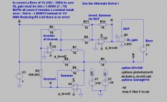
I like to know how much gain for a given error is needed in the stage which should be corrected. For this I try sch. EC1 versus EC2.
Regards
Heinz!
before some days I try to do some EC experiments.
For start I tested 2 different schematics to got a "feeling" for feedback EC ( I call simple so for myself, so can I better distinguish it from feedforward EC).
I use only inverting amps for the summers, because they have for this purpose the smallest error...as models ..and in reality!
I like to know how much gain for a given error is needed in the stage which should be corrected. For this I try sch. EC1 versus EC2.
Regards
Heinz!
Attachments
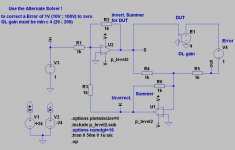
Now EC2, here is interesting, that I had to reduce R3 a bit to get in all cases also 0 error.
May be the reason will be explained from a person which know better mathematics than I!
I "like" this schematic more than EC1, because I can better "see" the positive FB through R1...without it works only with NFB.
May be the reason will be explained from a person which know better mathematics than I!
I "like" this schematic more than EC1, because I can better "see" the positive FB through R1...without it works only with NFB.
Attachments
Nixie said:What the hell is an "alternate" solver? Why are you spreading the incorrect English usage of the word that LTSpice unfortunately uses?
Using "alternate" to mean "alternative" is completely wrong!
Please, stop molesting the English language!
Please, stop molesting me!
Nixie said:.... impractical without feedforward.....
A patent untruth: error cancellation in this application is only required over the range 5KHz-20KHz. This, for practical purposes, is easily achievable.
For more practical tests I create a simple poweramp. I take it from the examples and added a bootstrap C and use complementary EF´s. With a inv. gain of 10 THD 20 was 0.039%.
After that I put it in a simple opamp symbol and try to reduce thd with both EC schematics.
Also I use the amp openloop with EC and find there is no real difference!
The improvement was quite remarkable: THD 20 drops down to 0.00042% without affecting to stability.
At last I tried a bridge connection, each amp with it´s own EC...
THD20 goes further down to 0.00019% !
I don´t have expected this good results, especially when I look at the BOM!
For further experiments I put all circuits in the attachment.
Regards
Heinz!
Attachments
With new "experience" I do a test with TOM´s schematic, he use the OPA541 as poweramp.
In the inverting mode one can use the input as a summer, so you need only 2 additional opamps for EC!
Also in this example the improvement is goog :
THD20 drops down from 0.0084% to 0.000082% !
Heinz!
In the inverting mode one can use the input as a summer, so you need only 2 additional opamps for EC!
Also in this example the improvement is goog :
THD20 drops down from 0.0084% to 0.000082% !
Heinz!
Attachments
To make further experience with "feedback EC" I grip the well known "Symasim".
In my model I had to change the compensation a little bit, and as alway I operate him in the inverting mode with a higher gain of 40 :
THD20 was 0.0124%.
After adding the 2 opamps for EC it reduces to 0.000126% !
When I tried him with a slewrate limited rectangle, which I usually use for a quick stability tests, I discover some asymmetry.
The reason for this is what Bob calls "dynamic crossover distortion".
A simple cure was the use of Tanakas biasing circuit.
After that the rectangle looks nice and THD20 go down to 0.000089% .
Heinz!
Edit:
My Symasim model has PSR @ 10kHZ -85dB.
The EC version has -103dB @ 100kHz!
Attachments
After all experiments I got the impression that "feedback EC"
is fairly simple to add, especially if the gain stage which should be corrected has a good bandwidth.
It seems to me, that it is a bit simpler when you not use it openloop.
The typically improvement @THD20 was 50...100 x !
At last I take my simple poweramp with very strong NFB and great bandwidth and try to "improve" him with my EC2 schematic.
Only with NFB THD20 is 0.000006%, but after applying EC I got more then twice, although I had no problems with stability!!
So I changed my EC opamps from LTC1122 to LT1632...and the result you can see below.
I had to thank all members of this thread...without this I had not enough motivation to make my own feedforward EC experience! 😉
Regards
Heinz!
Attachments
- Home
- Amplifiers
- Solid State
- Bob Cordell Interview: Error Correction