Resistance on the 2184, no power applied.
Black on pin 3, red on pin 4?
Black on 4, red on 5?
Black on 6, red on 7?
Black on 7, red on 8?
Black on pin 3, red on pin 4?
Black on 4, red on 5?
Black on 6, red on 7?
Black on 7, red on 8?
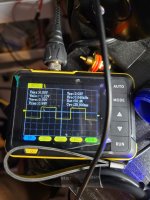
Confirm that there is no DC voltage across pins 3 and 5. If it's 0v, make a quick check of the previous resistances to confirm they're essentially the same.
No dc voltage present across pins 3 and 5 read 0.00v , can confirm all the readings stayed the same except the last reading is slightly less but still in excess of 2Mohms. I tested with 2 different multimeters to confirm these readings aswell. Is something about these readings off?
The readings are low.
Do you have another replacement that you could check out of the board to confirm that the readings are much higher?
Is the IC in a socket?
Do you have another replacement that you could check out of the board to confirm that the readings are much higher?
Is the IC in a socket?
The IC is not in a socket. Crazy enough it was replaced already I can check it against an extra I have.
Can confirm readings on the 2 extras are all in the Mohms. I can desolder the driver card again and remove the IRS2184 again and test outside the board.
If you do, check the same with the board out, IC in
The board pins with IC out
The desoldered IC
The board pins with IC out
The desoldered IC
Thank you I will look into that. That coupled with the electric desoldering pump I got for cheap should make easy work of this !
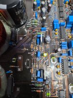
Besides the IRS2184, LM211 and J111 transistor on the driver card along with TC4452 banks and its regulator the 7812FA and its 4.8 ohm inductor. A with 1 diode labled (d54a reads .772v one way) which appears to have one leg connected to the low side gate resistor and the GND of the TC4452 pads was also replaced. I am combing through the board to see if there is any hidden shorts / blown resistors or open diodes.
What resistor values do you have between the driver board and the 4452 inputs?
I have conflicting information on this.
I have conflicting information on this.
Driver board Lo side output is pin 3 between that and pin 1 (input) on the TC4452 is a 1.5k ohm resistor (brown, green, red gold) measures around 998ohms with the multimeter .
I have two different diagrams. One has one driver board the other has two driver boards. They show 15k and 6.8 k where you have 1.5k and 680? ohm resistors.
Wasn't this a working amplifier?
Wasn't this a working amplifier?
- Home
- General Interest
- Car Audio
- Blown Sundown Salt 8 Amplifier