I think I'd replace the driver IC, in case it was damaged. Lift the 1.5k resistors to break the output of the drive from the main circuit. Does that give you low-side drive?
Did these ICs come from a reputable distributor?
Did these ICs come from a reputable distributor?
Ok I will replace with another 2184 and give it a test. Is there a way to know if the TL072 or LM211 is faulty ? Yes these parts were ordered through Mouser. I will try lifting the resistors. Just to go over the process I performed to see if I got low side drive. I connected the ground probe of the battery powered oscilloscope to the negative rail and probed pin 4 of the ir2184. Also probed the input pads of the TL4452 (no fets fitted). I tried dial in a signal using auto mode and also manually and tested with both DC / AC coupling to no avail. Thanks for the help perry I really do appreciate it.
Attachments

It sounds like you got it right.
If you connect a 10k resistor across pins 6 and 7 of the TL072, the IC should produce relatively clean audio at pin 7.
The output of the LM211 should swing like what you had previously with just a small amount of audio out of the TL072. I think those are OK. It appears that all is OK up to the input of the 2184.
OK will replace the 2184 when I get home and take a look at the TL072. A few questions so I may understand what is going on a bit clearer.
1. For the LM211 is the output only supposed to be on Pin 7 ?
2. is the purpose of the J111 (SOT-23-3) to act as a muting switch for the OP amp?
3. Do you know the amplitude of the drive wave that is supposed to be coming out of the 2184 and into the 4452 drivers?
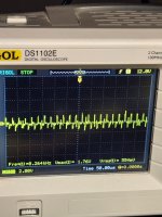
4. Why cant I see the drive wave but can see a square 40hz signal on the Lo of the 2184 when injecting a signal through the RCa's
Side note: when i had all of the TC4452's fitted and injected a signal I was able to see it on the gate pads where the low-side mosfets would be fitted.
Thanks !
1. For the LM211 is the output only supposed to be on Pin 7 ?
2. is the purpose of the J111 (SOT-23-3) to act as a muting switch for the OP amp?
3. Do you know the amplitude of the drive wave that is supposed to be coming out of the 2184 and into the 4452 drivers?
4. Why cant I see the drive wave but can see a square 40hz signal on the Lo of the 2184 when injecting a signal through the RCa's
Side note: when i had all of the TC4452's fitted and injected a signal I was able to see it on the gate pads where the low-side mosfets would be fitted.
Thanks !
1. Yes. Look up the datasheet
2. Yes, as far as I know.
3. The output amplitude of this type of IC is very nearly the DC voltage feeding each output section. Both the high and low side see about 12v so you should get approximately 10 or 11v of amplitude out of the high and low-side drives.
4. I don't understand the question.
2. Yes, as far as I know.
3. The output amplitude of this type of IC is very nearly the DC voltage feeding each output section. Both the high and low side see about 12v so you should get approximately 10 or 11v of amplitude out of the high and low-side drives.
4. I don't understand the question.
Thanks for the reply.
1. Was a bit confused because it also list pin 1 as an output but only saw a signal coming out of pin 7 but i see now it is setup for collector output with pin 1 tied to - vcc
2. OK thanks.
3. Ok that makes sense
4. Please disregard.
1. Was a bit confused because it also list pin 1 as an output but only saw a signal coming out of pin 7 but i see now it is setup for collector output with pin 1 tied to - vcc
2. OK thanks.
3. Ok that makes sense
4. Please disregard.
Double checked again and the LM211 is still functioning correctly with voltage swinging. What is feeding the input of the 2184 ? I'm guessing the output of the lm211 goes thru a few buffer transistors ??
Are the waveforms on the high-side drive and the input approximately 50% duty cycle?
Are you checking on the actual low-side output terminal of the IC or some other point?
Are you checking on the actual low-side output terminal of the IC or some other point?
with the 1.5k resistors soldered back it measures the same as before. I have not test high side drive yet, the high side has its TC4452's installed the lowside does not I am waiting for them to show up. Yes I am probing pin 4 of the IRS2184 as listed in the data sheet also have probed both sides of the 1.5k resistor
1. It shouldnt matter if not all the TC4452's are fitted right?
2. Do i apply a 9v to VS (-) and VB (+) ?
2. Do i apply a 9v to VS (-) and VB (+) ?
Why did you reinstall the 1.5k resistors before you finished testing?
1. Not if the output FETs are out of the circuit..
2. With no rail-rail oscillation, you need to supply voltage to the high-side.
1. Not if the output FETs are out of the circuit..
2. With no rail-rail oscillation, you need to supply voltage to the high-side.
1. I did it temporary to confirm... they are not installed currently
2. Can you please instruct me how to properly power the high side with a 9v battery, I remember you mentioned a trick to do it before ?
2. Can you please instruct me how to properly power the high side with a 9v battery, I remember you mentioned a trick to do it before ?
The 9v battery needs to be fully charged. Confirm 9v+
Connect
Vs to the negative terminal of the battery
VB to the positive terminal of the battery
If you have a 1 ohm 1/8 or 1/4w resistor, connect it in series with the battery.
Connect
Vs to the negative terminal of the battery
VB to the positive terminal of the battery
If you have a 1 ohm 1/8 or 1/4w resistor, connect it in series with the battery.

- Home
- General Interest
- Car Audio
- Blown Sundown Salt 8 Amplifier