Thank you for the clarification, whats crazy is when the amp blew there was no music playing and then a loud pop followed by lots of crackling, no protect and no fuses blew basically had to wait for the power section to finish cooking :/. When it comes to testing the drive signal on the output I know there should be a drive signal on the gate of the low sides (is it necessary to load it down when testing like the PS?) as for the high side do you have to play a signal through the rca's to get a drive signal ? Thanks !
It's best to load. It gives you a better idea of the condition of the drivers.
For most amps with the floating high-side drive (like the 2184), you often have to supply the high side B+ since there are no outputs in the amp (which typically help produce the high-side supply). I use a 9v battery. There may be other ways to test but I haven't tried them all so I won't recommend them.
Does this amp have 12v measured directly across the high-side supply pins on the driver IC with no outputs in the circuit?
Last edited:
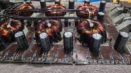
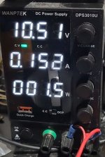
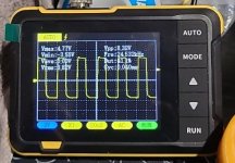
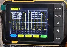
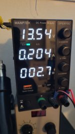
Thanks for the info, I am not able to test any voltages on the output at this moment, some traces were damaged and have been doing some repairs on that before I power up the Output section again. I had a chance to load down the drive signal on the PS today with the capacitor you recommended and the drive signal looks good so I'll start populating the mosfets again and report back about the output section voltages. I had some spare 22ohm +- 1% resistors laying around so swapped the gate resistors out anyway. Here a pic of the signal while loaded down, I have the amp current limited on a power supply set to 9v for testing right now. Thanks ! 🙂 I appreciate all the info I have been taking notes,
Attachments

The 9v I was referring too was for something else. You can test the supply at 13.5v (or something close to normal).
The voltage on the drivers for the power supply should have an amplitude of nearly the B+ supply voltage. I don't know why you're getting just over 4v. Test at higher B+ voltage to see if the amplitude goes higher (and near B+ in amplitude.
The voltage on the drivers for the power supply should have an amplitude of nearly the B+ supply voltage. I don't know why you're getting just over 4v. Test at higher B+ voltage to see if the amplitude goes higher (and near B+ in amplitude.
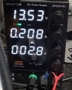
haha I know the 9 volts you were referencing was for the output high side drive signal. I just usually test amps at 9v and limit the current just to be sure nothing explodes. When I get home I'll try 13.4-14.2 with a 3amp limit and see what amplitude I get and report back. Thanks !
Some amps won't power up at less than 10.5v due to low-voltage protection. With no FETs in the circuit, there is very little that could be damaged.
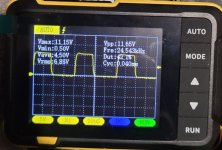
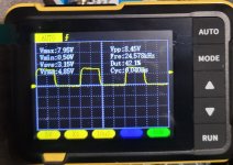
Oh okay thank you for that info I thought because they rate the amp usually around 9v min that would be okay. I upped the voltage to 13.5 as suggested and the drive signal looks a bit better, I also included pic of it at 10.5v for reference.
Attachments
Sorry for the crazy late reply. Life happened and I had to set this project to the side for a bit. I am at the part where I have to test the high side drive signal, the method of injecting 9v are you meaning supply voltage to the 2184?

I believe in #29 both were different input voltages. Here is a photo with a 13.5v input. I have yet to populate the PS section with mosfets, I was mostly inquiring about the High side drive signal for when they come in and I can power the amp up partially.
Attachments
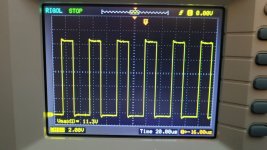
No outputs yet, was doing research to see if I could drop in the 24n50F's with no modifications to the circuit but it doesnt look plausible so I will be ordering the stock 24n40f's. I do not believe it was taken using differential mode. just probing the gate on the ps mosfet pads with a 13.5v input going to the amp.
OK. For some reason, I thought that was for the low-side output FETs, probably because there was a discussion about the high-side 9v supply.
Do you have low-side drive from the audio driver IC? You'll either need to use differential mode or use a high vertical amplifier setting. You need to use DC coupling for the waveforms to be of any use.
If you don't know how to use differential mode:
A differential input uses two inputs to produce a single waveform. The simplest way to get a differential input is to use a differential probe. A differential probe has two signal leads and a mixer amplifier built into it. It feeds the scope a normal signal (a composite of the two signals input into the differential probe). The problem with differential probes is that they're expensive.
The alternative is to use two scope probes and and both inputs of your oscilloscope. This is how you have to set up your scope:
Two probes
Both scope inputs used
Input set to add
Both channels set to DC coupling
Both channels set to 'cal'.
Both vertical amps set to the same voltage
Ch2 input set to invert
Bandwidth limited (works best for most measurements in car amps)
Trace aligned to the reference line on the scope's display
Ground leads for both probes connected together (not always necessary)
After setting up the scope, you need to confirm that it's working as it should. With the vertical amp set to 5v/div, touching the probe that's connected to Ch1 to the positive terminal of your 12v power supply should make the trace deflect about 2.5 divisions up from the reference (like it always does, seen below). Doing the same with the probe connected to Ch2 should make the trace deflect down about 2.5 divisions. Touching both probes to the positive terminal of the 12v power supply should cause no deflection. If it does, something isn't right.
I know that this may not be as simple as the isolated scope but if you take the time to learn it one time (even if it takes an hour or more of your time), you have that knowledge and this tool to use for the rest of the time you need to use a scope. Using the analog scope will give you much larger and cleaner waveforms.
Waiting for TC4452's to come in and I will check low side. Thank you for the information I do not have differential probes (i may buy some) and I will try the method you spoke about and report back.
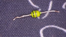
Do you know what this component value this component is labeled L5 on the board? I believe it is an inductor but i haven't seen many with only 3 bands. This inductor was feeding voltage into a DIODE network that fed the 12v regulator?.
Do you know what this component value this component is labeled L5 on the board? I believe it is an inductor but i haven't seen many with only 3 bands. This inductor was feeding voltage into a DIODE network that fed the 12v regulator?.
Attachments
All you need is two normal probes $5 each on ebay.
47uH inductor. They typically read about 3-5 ohms.
47uH inductor. They typically read about 3-5 ohms.
OK, I do have a second probe I will test with that. Ok this part was OL will replace. Is the inductor a 1w part?
Wattage? That's not generally an inductor spec. Someone will correct me if I'm wrong.
Someone here will have a good part number but I don't have anything.
Order the same size (or as large that will fit for the lead spacing). Find one in the 3-5 ohm range.
This may work if it fits:
https://www.mouser.com/ProductDetai...=sGAEpiMZZMv126LJFLh8y8rwpbbr88RteK3dQRCDZzA=
Someone here will have a good part number but I don't have anything.
Order the same size (or as large that will fit for the lead spacing). Find one in the 3-5 ohm range.
This may work if it fits:
https://www.mouser.com/ProductDetai...=sGAEpiMZZMv126LJFLh8y8rwpbbr88RteK3dQRCDZzA=
Last edited:
- Home
- General Interest
- Car Audio
- Blown Sundown Salt 8 Amplifier