cfp for the main pass cascode?perhaps a jfet (k170) driving a D45H11 (as per teddy-reg)
Will that introduce a risk of oscillation?
A cheap bf244b or bf245b driving a medium power fast BJT.
The present cascoded CCS j1j3 is wasted with only 40% of it's current passing the first LED. This must be changed.
Compare this to the D4 current passing R13, here it is >99.5% That is a far better place to insert a cascoded CCS for the LED current.
Are there other simple ways to improve this?
Why is it that everytime someone comes up with a valid question or concern, immediately the complete design is changed?
You're not getting anywhere this way.
Andrew had a good point that the Hfe of the pass transistors must be above a minimum value to avoid cutting off the LED string. So, I naively thought, OK, we select a transistor with enough Hfe. What's wrong with that??
Fairchild, for example, sells BD's with 3 classifications. The -16 has min Hfe of 100. For added margin, double the current through the LED string. Issue solved.
Jan Didden
There is nothing wrong with that.janneman said:.......... the Hfe of the pass transistors must be above a minimum value to avoid cutting off the LED string........................ we select a transistor with enough Hfe. What's wrong with that??................. The -16 has min Hfe of 100. For added margin, double the current through the LED string.
It's a valid solution that gets better performance.
Can we measure this improvement? Is this what gave the poor results on the prototype?
Now to more detail.
Select BD140s with hFE>100 for the CCS.
Double the fet CCS current to 7mA.
With 150mA entering the CCS the first LED will pass ~57% of the fet CCS current. Still way short of the 90% I recommend and not in the same playing field of the >99.5% of the other led string.
What if one cannot source BD140s with hFE>100?
Is there a more suitable transistor that will suit 150mA CCS current?
I don't need it for my personal use, but others may require this improved transistor pair.
BD140's with Hfe>100 or $ 0.14 ...
But I'll check my lib to see if there are even better ones.
BTW The problems with the prototype were from a different nature. Still, your recommendations can very well have a measureable improvement.
Jan Didden
But I'll check my lib to see if there are even better ones.
BTW The problems with the prototype were from a different nature. Still, your recommendations can very well have a measureable improvement.
Jan Didden
Andrew had a good point that the Hfe of the pass transistors must be above a minimum value to avoid cutting off the LED string. So, I naively thought, OK, we select a transistor with enough Hfe. What's wrong with that??
With real FETs you're stuck anyway with what Idss range your specimen provide. My 60 BF245A are all between 2.5 and 3.5 mA, (BF245C were 18-20mA) - this is enough in my current prototype, but I would again suggest to select your JFETs for higher Idss or get BF245B from the start, that way you can use them in both positions.
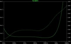
Nice flat in the audio band. Lets see how it holds up on a real pcb
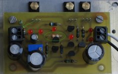
Here is a picture of my current prototype, which I offer for tests, off course. This is before I removed the inductor in place of R8 (green circle) Actually, I will make some minor corrections to the layout, to better acomodate all components (I have the sensing resistor and the Zener under the board, and R9 is too close to the output connectors), and create a negative version as well, hopefully by end of next week.
One more issue with the current circuit: the variable resistor that was in parallel to R10 in twitchies last picture will need to go in parallel to /or in place of R4 (upper resistor). Otherwise, the maximum resistance (potentometer open) will set the minimum voltage and the further you turn down the potentiometer the higher the voltage goes, raw supply permitting. And yes, this had me confused for a moment when I tested the circuit.
Attachments
BD140 Q5 must be replaced with a high hFE device that can carry at least double your intended pass current. A suitable spec would be hFE>300 and Icmax>300mA.
BD140 Q6 must be selected for hFE >150 over the whole current range you intend to pass. A more suitable device should be found. J1 needs to be >8mA Idss and R3 set to achieve at least 6mA through the FET CCS. A low pinch off voltage, high gm device is more suitable here (maybe k170bl).
The current circuit works fine for currents up to few hundred mA and I am not sure if you could easily come up with a simple circuit that fits a much wider range. I tried different CCS (VBE multiplier with Mosfets) and they were not as good - in simulation.
For Q5 I tried also different transistors and got a small improvement but not as much as you might expect. And a TO92 device would limit current due to it's dissipation limit. Provided that you get BD140-16 - which I have off course 😀 - I think you will be ok.
Why is it that everytime someone comes up with a valid question or concern, immediately the complete design is changed? You're not getting anywhere this way.
Could not agree more.
Could you do something for me while you've got it running so well - Will it still function with a load of 250mA @ 25volts with a shunt current of 100ma ( 40% of o/p)?
And could you also try out the original way of running the led current directly to groung instead of into the zener - just to confirm.
Not sure if your first question was answered but you should still be fine. Note though that Q2 (BD139) has to dissipate the whole energy in case your load is not connected (or dies). This is now more than 6 Watts and I would not go much farther with this package. A D44C type transistor might be even better.
Regarding your second question, I was trying both and saw a minor improvement with the current going through the Zener. My point is that Zeners (and LEDs) perform better with higher currents, and may have lower noise (irrespective of the simulation).
Mrupp,
a cascoded FET CCS is wasted when ~half it's load is not from the LED it is trying to hold constant. A single resistor would work, a single FET CCS would be slightly better, but I somehow doubt that adding a cascode will give an audible or measurable improvement.
We must increase the LED current as a proportion of the CCS current drastically to get some real benefit from a good CCS.
Just using a 245c alone ~10mA to 12mA improves that proportion.
Replacing the first BD with a high hFE transistor improves that proportion.
Increasing the hFE of the second BD improves that proportion.
AndrewT,
I am not sure if I understand you entirely. As I suggested repeatedly use a JFET that has enough current so that the portion going into the bases of Q5/Q6 does not cause a problem. The cascode was put in the improve the bandwidth and the impedance of the current source, NOT to cope with insufficient current or wrongly selected devices. As for how audible that is I cannot comment, but looking at the small extra costs and extra board space this is a no-brainer and I will use the cascoded version. Lastly, for the transitor selections, we need to agree on one particular package and not change it constantly.
I am not sure if I understand you entirely. As I suggested repeatedly use a JFET that has enough current so that the portion going into the bases of Q5/Q6 does not cause a problem. The cascode was put in the improve the bandwidth and the impedance of the current source, NOT to cope with insufficient current or wrongly selected devices. As for how audible that is I cannot comment, but looking at the small extra costs and extra board space this is a no-brainer and I will use the cascoded version. Lastly, for the transitor selections, we need to agree on one particular package and not change it constantly.
I think what Andrew means is that we used the CS to try to keep the ref voltage generated by the LED extremely constant. But the CS not only sinks the LED current but also the pass transistor base current. Iled =Ics-Ibase. Since the latter varies in relatively large proportion of the total, the LED current also varies relatively large. So, even with a super-duper ideal CS you STILL have LED current variations. Thus, that CS and especially the cascode for it is pretty much wasted and a resistor would be almost as good.
However you skin this, you always come back that you want small Ib (variation) relative to Iled. Maybe a Darlington in a TO126 would be a good option. Some of those TIP types? You lose a tiny bit of dropout headroom but it's probably worth it.
Jan Didden
However you skin this, you always come back that you want small Ib (variation) relative to Iled. Maybe a Darlington in a TO126 would be a good option. Some of those TIP types? You lose a tiny bit of dropout headroom but it's probably worth it.
Jan Didden
Lots of changes have been done already to the topology of the circuit and we still consider it a Cetoole so I see no problem changing the ccs to a bjt+fet or whatever if this will yield a better regulator to the benefit of all.
What Colin did was planting a seed that has germinated to the present regulator after many tests and sims from many voluntary worldwide contributions… that’s also the beauty of this effort.
-As Jan said:
“This is a great thread! Lots of interesting things and ideas from all over!”
What Colin did was planting a seed that has germinated to the present regulator after many tests and sims from many voluntary worldwide contributions… that’s also the beauty of this effort.
-As Jan said:
“This is a great thread! Lots of interesting things and ideas from all over!”
Someone here did some research on zener / LED noise and I thought he concluded a zener was better that multiple LED's as long as 8.2V was avoided ( because 8.2V falls between two operation modes is subsequently noisier than other values )
so perhaps a 4.7V or 5.1V zener would be better ?
just a thought
mike
so perhaps a 4.7V or 5.1V zener would be better ?
just a thought
mike
I hear you guys. Perhaps my noise tests were wrong, but the LEDs I have, even three in series, were not as noisy as any diodes. Whatever the case though, the ccs was just a wild idea thrown out there for perusal, not exactly a serious proposition.
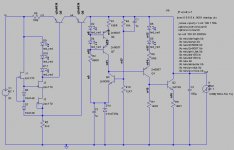
This is the alternative ccs.
I cannot question that this looks interesting. Will try myself after easter, since I need to redo my layout anyway I might try this version. Or is there anything still to streamline in the schematic? I thought I saw something similar in a recent shuntreg (Syn08 ????).
Someone here did some research on zener / LED noise and I thought he concluded a zener was better that multiple LED's as long
I was looking at Christer's measurement on LED and Zener noise, and it appears that only zeners with higher voltage (12V in his example) were as low in noise as LEDs were, in the lower voltage range noise was several times as high at least. Which might make LEDs also attractive as the main voltage reference?
thanks for that clarification - but I still seem to remember he said that he did not recommend strings of LEDs - I will check and post what I find
mike
mike
- Status
- Not open for further replies.
- Home
- Amplifiers
- Solid State
- Bipolar discrete shunt regulators