steenoe said:This is the latest schematic. Still needs the last few changes to be added.
http://www.diyaudio.com/forums/showthread.php?postid=1733072#post1733072
🙂
I would change Z2 to an LED, and R5 to an LM334 CCS (with 12 ohms as set resistor). This does limit Vin to 40V though, if that is a problem, make a provision to put a zener in series with the LM334.
RV15 is the trimpot. I would just use a fixed resistor here; the absolute Vout is not critical and the resistor can be easily calculated.
What I haven't checked, but what I would put on the new pcb, is a resistor from Vout to the top of the reference zener. That way, we could get some current into the zener that is independent from the current through the error amp Q3. Q3 current varies with load and (a bit) with input ripple so keeping the zener current relatively independent helps also. Don't know how big the effect will be, but worth a try.
Jan Didden
Onvinyl said:
That shouldn't be too though, especially with a shunt reg, since a shunt reg splits the loops (raw supply and regulated supply) quite effectively.
I agree. That's what I way trying to show in that LTspice sim. Even a rudimentary layout with just one straight ground and power track can be arranged such that PSR is pretty much a non-issue.
The effective reduction in output impedance due to the earth return currents from the load are an other issue though!
I've actually layed out and built that regulator, layed out from left to right as drawn in the schematic with just a low impedance top and bottom ground plane. PSR tested as good as expected. In theory the output impedance isn't as good as it could be with elaborate star point earthing, but this is irrelevant in my case as for the intended application the load only draws a dynamic current of about 50uA.
Layout considerations depend a lot on the application.
Cheers,
Glen
Guys,
I really want to understand what's the reasoning for building such a discrete regulator. I understand how they work, I have simulated their performances (and they seems to be decent) but I have not build and measured one.
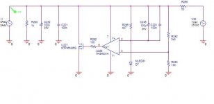
However, I have simulated, build and estimated the performances of the parallel regulator in attached schematic. The measured results are really very, very good, beyond what I think it will ever be needed for audio and BTW, they match the simulations within 25% (or at least that's how much I bothered to look into). Note that this is a completely not optimized design, I haven't even bothered to try a current source or other references beyond a LED. BTW, the output noise is comparable to the Jung serial regulator.
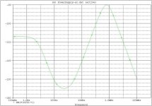
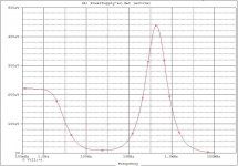
To compare with the discrete version, I'll put in the next two posts the PSRR and the output impedance for a +30V version (mine are +/-17V).
I'll let you compare the performances and the complexities/sizes/costs. Again, beyond a) limited to 30V output and b) not that much fun to deal with, I don't see much of a reason why one would build the discrete version.
I really want to understand what's the reasoning for building such a discrete regulator. I understand how they work, I have simulated their performances (and they seems to be decent) but I have not build and measured one.
However, I have simulated, build and estimated the performances of the parallel regulator in attached schematic. The measured results are really very, very good, beyond what I think it will ever be needed for audio and BTW, they match the simulations within 25% (or at least that's how much I bothered to look into). Note that this is a completely not optimized design, I haven't even bothered to try a current source or other references beyond a LED. BTW, the output noise is comparable to the Jung serial regulator.
To compare with the discrete version, I'll put in the next two posts the PSRR and the output impedance for a +30V version (mine are +/-17V).
I'll let you compare the performances and the complexities/sizes/costs. Again, beyond a) limited to 30V output and b) not that much fun to deal with, I don't see much of a reason why one would build the discrete version.
Attachments
I agree that there are millions of ways to skin this particular cat. But, being diy, I often enjoy discovering and building stuff, even if in some far away corner of this universe there may be someone who can do me one better.
It's the enjoyment of finding out and getting it to work that counts for me and for a lot of other people in this thread.
I would be disappointed if this design keeps on swaying to and fro without actually getting done!
Let's stick with the original design, finetune it, and getting it going. As a reg, it'll be pretty good and worthwhile your work and mony.
Jan Didden
Jeez, Ovidiu, your reg is depressingly simple 😀
As I always distrust the computer, maybe you find time in a bored moment to post some measured numbers. If that toy comes close to a Jung/Didden in the real world, I'm deeply impressed.
So much simplicity demands being used in the next project 😉
Have fun, Hannes
As I always distrust the computer, maybe you find time in a bored moment to post some measured numbers. If that toy comes close to a Jung/Didden in the real world, I'm deeply impressed.
So much simplicity demands being used in the next project 😉
Have fun, Hannes
Schematic?
Seems his site prefers selling his stuff, no schematic. It's ok, but then I don't understand your reply 😉
Have fun, Hannes
Seems his site prefers selling his stuff, no schematic. It's ok, but then I don't understand your reply 😉
Have fun, Hannes
janneman said:
Let's stick with the original design, finetune it, and getting it going. As a reg, it'll be pretty good and worthwhile your work and mony.
Jan Didden
Yes, we will do that...
I have troubles with my IP so some emails have not gone thru, will take a couple of days to organize work.

AndrewT said:what effect does changing R7 to a CCS have?
I'm not home now, but assuming R7 is the resistor that sets the current for the bias of the input CCS/cascode: a ccs at this position makes the bias more independent from the input (ripple) voltage, so improves PSRR. If you use say 3k there, there is a voltage divider between the LED/diode and the 3k that leaves a bit of ripple on the CCS base. (Also as a result from the varying base currents). You ideally want R7 very large, but you need some current through the LED/diode, so that is a conflict. With an LM334 you can have your current as well as high impedance.
Jan Didden
h_a said:Schematic?
Seems his site prefers selling his stuff, no schematic. It's ok, but then I don't understand your reply 😉
Have fun, Hannes
principle - shunt part with OP as error amplifier
Seems his site prefers selling his stuff, no schematic. It's ok, but then I don't understand your reply
I think Alan was one of the first to propagate super shunt regulators. Btw., I did buy his preamp cookbook and the regulator schematics is in there - I found the book well worth the buy. He is making a living from his developments and I understand that he does not offer everything for free. Btw., he shows some very interesting phono preamp schematics on his WEB site, I think they are sufficiant contribution to the diy community ...
Does this post together with the attachment help?
This is Emile Sprenger's regulator version for high voltages. FWIW, I looked at numerous shuntreg designs that have been around for some time and all use opamps as error amps - either discrete or integrated - but that may just be convenience. John Broskie has a number of blogs about shuntregs (including some feedworward designs) and many of his examples, although with tubes, resemble the ctoole regulator. So it may well be worth a try. My examples
1. Allen Wright: Error amp LF357 (or better), shunt element IR MOSFET
2. Manuel Huber: Error amp discrete BJT Opamp, shunt element IR MOSFET
3. Emile Sprenger: Error amp OPA655P, shunt element IR MOSFET
4. Walt Jung: Error amp BJT diff pair, shunt element triple darlington – no series CCS (but it looks like he is working on a new design ?)
5. STAX AB100: discrete BJT opamp, BJT shunt element
6. Borbely: discrete JFET diff pair, shunt element Toshiba MOSFET (much lower Vgs)
R7 is the main shunt B to E resistor. 100R with ~ 6mA passing
It would substantially increase the loop gain but you will have a hard time finding a CCS that works well with just 0.6 - 0.7 Volts.
Also, I had some concerns about the Q5 / Q6 current source but my (maybe incompetent) spice simulations comparing it to an alternative CCS (similar to the Borbely CCS) show that it fares quite well even at 100 or 200 mA, and using a CCS in place of R5 is a substantial improvement.
This leaves one last concern, i.e. that the voltage drop accross Q4 / Q7 has too much voltage.
syn08 said:Guys,
I really want to understand what's the reasoning for building such a discrete regulator. I understand how they work, I have simulated their performances (and they seems to be decent) but I have not build and measured one.
.
That explains everything
 Darn, my concern about having this discussion in the SS forum, was comments like this. If "some"one has no constructive ideas about the Toolereg, why bother posting in this thread?? Please go and sim some more, and live happily!
🙂
steenoe said:
That explains everything
🙂
That explains everything
. Darn, my concern about having this post in this particular thread was comments like this. If you didn't noticed, I have built the opamp version (which, I just found, seems to be very similar to some well known commercial solutions) and it measures much better than this discrete version simulates. Go figure... Data available by request.
But then you can build whatever fits you, performance is not the one and only criteria. I'll drop it here.
🙂
- Status
- Not open for further replies.
- Home
- Amplifiers
- Solid State
- Bipolar discrete shunt regulators