steenoe said:
That explains everythingDarn, my concern about having this discussion in the SS forum, was comments like this. If "some"one has no constructive ideas about the Toolereg, why bother posting in this thread?? Please go and sim some more, and live happily!
🙂
 😀
😀syn08 said:[B
If you didn't noticed,
🙂 [/B]
I noticed that ya build nothing! So whatever comment you have to share, I couldnt care less😉
🙂
steenoe said:
I noticed that ya build nothing!
Really, you think so? 🙂 Have you checked around? 🙂 Througly? 🙂 Perhaps you may want to try again? 🙂
But then
whatever comment you have to share, I couldnt care less 😉
steenoe said:
I noticed that ya build nothing! So whatever comment you have to share, I couldnt care less😉
🙂
syn08 said:
Really, you think so? 🙂 Have you checked around? 🙂 Througly? 🙂 Perhaps you may want to try again? 🙂
But then
syn08
Lucky Luke was famous for drawing a gun faster than his shadow.
Maybe steenoe is moving his fingers a lot faster than his brain.
He claims that you have built nothing, the only thing I can say I feel sorry for him.
Cheers
Stinius
Dear Jan,
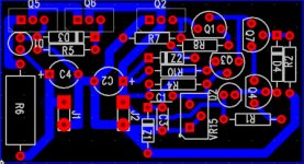
Here is my newbee's attempt on the layout. I hope it is not too bad. I am using PADS, so some of the outline patterns are odd (e.g, J1, J2 are input and output terminals, respectively.) I have add R10 to provide current from the regulated output to the reference zener Z1, but still using R5 instead of LM334.
Best Regards,
KF Tam
janneman said:More measurements.
Changed R8 to 82 ohms + yellow LED (~2V). Works fine, and will allow use for 5V reg.
Changing R3 to LED only increases dropout, not usefull.
Then I replaced R5 with an LM334 CS (Rset=12 ohms, ~6mA). Some improvement, not much.
Then I measured the PSRR directly across the regulator sense points, between top of R4 and bottom of VR15. Bingo: a more than 20dB improvement! PSRR at 1kHz now -65dB. Residual close to noise (~ 60uV).
So the problem is the layout. If you want good performance at the output terminals, you must sense the errors at the output terminals. Top of R8 with its own trace to the output terminal, bottom of VR15 and bottom of ref zener Z with their own traces to the output gnd terminal. E & C Q2 with their own traces directly to the output terminals. Also C2.
I bet that Rout will also be much lower with those changes.
Jan Didden
Attachments
syn08 said:Guys,
I really want to understand what's the reasoning for building such a discrete regulator. I understand how they work, I have simulated their performances (and they seems to be decent) but I have not build and measured one.
No further comments. I beleive everyone would appreciate, if we could be spared for more of this sort.
steenoe said:No further comments. I beleive everyone would appreciate, if we could be spared for more of this sort.
Indeed, I did not build this discrete parallel regulator and, for the reasons I already mentioned, don't plan to anytime soon. But I understand your stance, good luck with the Group Buy initiative, you certainly look very motivated to succeed!
Please go and sim some more, and live happily!
Steenoe, I'm not interested in emotional fun of that sort usually, but that was by far off the fence.
This is not your thread.
If you don't understand technical contributions I may as well tell you to stop posting because you don't understand nuts.😉
In case you missed, the original Toole-reg had very poor performance as Jan showed. Every technical help here lead immediately to a great improvement that benefits all that want to build the Toole-reg.
Syn08 has developed and build and measured his amps that push distortion specs to their limits, if you would have spend a second looking at his website you would have noticed. If I was interested in the Toole-reg, I would appreciate his help greatly.
Anyway, even if Syn08 was a purely hobbyist simulator guy, that's no way to treat interested people.
Go and hide below your bed - and come back then 😀
Have fun, Hannes
To all,
We are moving forward quite nicely with the refinements to this regulator thanks mainly to Jan’s efforts and also to so many others that have contributed before.
Our next task is the layout of the board to meet Jan’s outlines and this work will be done by Colin who was kind enough to accept this responsibility; so in a few days we can expect results.
Cheers,
Our next task is the layout of the board to meet Jan’s outlines and this work will be done by Colin who was kind enough to accept this responsibility; so in a few days we can expect results.
Do we really have a final schematics and if so can you please post it?
http://www.diyaudio.com/forums/attachment.php?s=&postid=1733072&stamp=1233638713
but Z2 is upside down and it's not final yet.
but Z2 is upside down and it's not final yet.
Thanks, and I thought I was even more confused than I already am. My understanding is that the schematics you posted is not exactly the final result?
The most fundamental thing that is missing here is the current source and biasing resistor instead of R5 (or under R5 - this would remove the voltage limit for the LM334). It has a substantial influence on the current source performance and I thought Jan recommended to put this in. Btw., the LM334 has the same footprint as many JFets so one could use either on the finished board.
Another suggestion from Jan is to replace VR15 with a fixed resistor. It is less convinient but may be better. Or alternatively both in parallel (most current through the resistor and a small portion through VR15 for adjustement).
Another "request" for the layout: For D3 and D4, can you put in an extra solder joint so that one can optionally use an LED, would give some more flexibility.
P.S. I know this would be asking too much, but how about an emitter resistor under Q2?
Z2 should be a LED as well. I'm not sure we need an Re for Q2. Glen's rationale is OK (limit loop gain) but I think the same can be done with the R7/R8 ratio.
What do you think Glen?
Jan Didden
What do you think Glen?
Jan Didden
Z2 should be a LED as well. I'm not sure we need an Re for Q2.
Jan, we could even cascade 2 red leds, this would fully compensate the voltage drop of the D2 + D4, and those who prefer a Zener would have the space to put in a zener - so just 2 more holes in the PCB. It could then be the cheap red LEDs and they are indeed cheap.
About Re, it is just a suggestion but would add the convenience of measuring the shunt current.
MRupp said:
Jan, we could even cascade 2 red leds, this would fully compensate the voltage drop of the D2 + D4, and those who prefer a Zener would have the space to put in a zener - so just 2 more holes in the PCB. It could then be the cheap red LEDs and they are indeed cheap.
About Re, it is just a suggestion but would add the convenience of measuring the shunt current.
Yes, good points. The only reservation I have about that Re is that it would/might decrease performance. But as you say, what's 2 holes on a pcb between friends, eh? 😉
Jan Didden
Guys,
as someone whohas used current sourced shunt regs in everything he's built for 30 years, tube and solid state, I STRONGLY suggest the addition of a 1 or 10R reistor to enable being able to measure the actual shunt current.
I can tell you from this practical experience, it's a great help when setting it all up - other wise you have to either guess, make severalmeasurements and then some calcs, or hold the shunt transistor in your pinkies and see if it's cold, getting warm, or too hot.
Regards, Allen (Vacuum State)
With R5 instead of a CCS one might experience a surprise when checking, whether a shunt regulator is really inherently protected against a shorted output...
At least I had such a surprise with a similar circuit...
Rüdiger
At least I had such a surprise with a similar circuit...
Rüdiger
Allen Wright said:Guys,
as someone whohas used current sourced shunt regs in everything he's built for 30 years, tube and solid state, I STRONGLY suggest the addition of a 1 or 10R reistor to enable being able to measure the actual shunt current.
I can tell you from this practical experience, it's a great help when setting it all up - other wise you have to either guess, make severalmeasurements and then some calcs, or hold the shunt transistor in your pinkies and see if it's cold, getting warm, or too hot.
Regards, Allen (Vacuum State)
Allen, I just measured the total current with no load across R6 and that gives me the shunt current +/-5%, good enough for a quick check.
But, again, if people find it comfortable, why not.
Jan Didden
Onvinyl said:With R5 instead of a CCS one might experience a surprise when checking, whether a shunt regulator is really inherently protected against a shorted output...
At least I had such a surprise with a similar circuit...
Rüdiger
With a short, the total Vin comes across the CCS. That *might* be a problem, but I can't see anything otherwise. Was it overvoltage?
Jan Didden
- Status
- Not open for further replies.
- Home
- Amplifiers
- Solid State
- Bipolar discrete shunt regulators