janneman said:
So the problem is the layout. If you want good performance at the output terminals, you must sense the errors at the output terminals.
Surprised? 😀
I've concluded quite some time ago that the fanciest (parts quality wise) Jung-Didden regulator with a poor layout is worse than a honest LM317.
OTOH, a LM431 and a MOSFET gives about (or better) performance as these discrete designs, true, only up to a couple of hundreds KHz. And that with a resistor as current source 😀 A LM329 reference, a MOSFET and a decent wideband opamp pushes the same up to a few MHz. That's all that audio will ever need.
I've concluded quite some time ago that the fanciest (parts quality wise) Jung-Didden regulator with a poor layout is worse than a honest LM317.
True but we work under the assumption that we can come up with a perfect layout 😉
syn08 said:
Surprised? 😀
I've concluded quite some time ago that the fanciest (parts quality wise) Jung-Didden regulator with a poor layout is worse than a honest LM317.
[snip]
Not surprised. You may recall that the J-D regulator used remote sensing for just that purpose 😉
Jan Didden
Onvinyl said:Hi,
I didn't intend to diss this regulator. The proposed regs (and mine as well) are all relativly close (also add the one of lumba here). They have a main CCS, a voltage reference, a gain boosting stage and a main shunt device. That's it.
We probably only have to chose the stiffest CCs, the lowest impedance and least noisy reference, reasonable gain factor and a large bandwith shunt device, all in the boundaries of KISS.
Just a proposal. I'm not in the GB (yet) but I'm trying the same since some time (making a few parts, best possible shunt reg).
Rüdiger
Thanks Rudiger for your comments, I did have a look too to your Reg. I am a bit confuse to make remarks since no specs availabe for any of these designs that could make sense to compare.
janneman said:More measurements.
Changed R8 to 82 ohms + yellow LED (~2V). Works fine, and will allow use for 5V reg.
Changing R3 to LED only increases dropout, not usefull.
Then I replaced R5 with an LM334 CS (Rset=12 ohms, ~6mA). Some improvement, not much.
Then I measured the PSRR directly across the regulator sense points, between top of R4 and bottom of VR15. Bingo: a more than 20dB improvement! PSRR at 1kHz now -65dB. Residual close to noise (~ 60uV).
So the problem is the layout. If you want good performance at the output terminals, you must sense the errors at the output terminals. Top of R8 with its own trace to the output terminal, bottom of VR15 and bottom of ref zener Z with their own traces to the output gnd terminal. E & C Q2 with their own traces directly to the output terminals. Also C2.
I bet that Rout will also be much lower with those changes.
Jan Didden
Jan
Greatly appreciate your effort in testing the reg this far and for all your suggestions and find your remarks encouraging that we are very close of an optimal design for a simple discrete shunt regulator.
Based on the above I think is worthwhile to continue working on this reg and definitely we would redo the layout to include your mod suggestions and change the sense points too but still unsure if we should include the ground plane as we have it on the proto boards you have.
Anyway, we will wait for your last test results and remarks and maybe you could summarize the test result measurements (in layman terms?) for all to have a general idea on the performance of this regulator.
Thanks much again
😎
kf_tam said:
I have search through these and some other discrete designs,
It seems real life performances are not readily available 🙄 :
I may have missed some other important designs.
Best Regards,
KF Tam
You really did your homework, nice to see all these designs linked here.
There are some very nice ones there specially the one from Glen K which seems well documented (and hi performance?), hadn’t seen it before and certainly one to consider even thou a bit more elaborated or complex than the Toolereg.
>Thanks for your input.
😎
apassgear said:the one from Glen K which seems well documented...
Hi
On the theoretical side, one thing I should have made clearer in that thread, WRT the dominant-pole frequency compensation achieved with the output filter capacitor, is that it relies (for adequate gain margin) on the gm of the “VAS” stage being finite - The “VAS” stage in this case being the common-emitter shunt transistor. In some cases a small emitter degeneration resistor may be required for the shunt transistor to ensure stability.
Cheers,
Glen
jameshillj said:Yes, a 0.1R SMDl, with maybe a 1nF bipass, yes?
It should be non-inductive and a bypass cap is a no-no because that would defeat the whole purpose, from this frequency compensation POV.
Think of the shunt transistor as a common emitter amplifier whose voltage gain is equal (approximately) to the collector impedance divided by the emitter resistance. At HF the output shunt capacitor will appear as roughly a short, its minimum impedance limited by its ESR and ESL.
The emitter resistance of/for the shunt transistor must be high enough so that the voltage gain of this stage is reduced at HF to well below unity, to account for the gain (divided by the feedback ratio) of the error amplifier preceding it. If it doesn't then your circuit will likely satisfy the Barkhausen criterion for oscillation

Hope that makes sense!
Cheers,
Glen
apassgear said:Jan
Greatly appreciate your effort in testing the reg this far and for all your suggestions and find your remarks encouraging that we are very close of an optimal design for a simple discrete shunt regulator.
Based on the above I think is worthwhile to continue working on this reg and definitely we would redo the layout to include your mod suggestions and change the sense points too but still unsure if we should include the ground plane as we have it on the proto boards you have.
Anyway, we will wait for your last test results and remarks and maybe you could summarize the test result measurements (in layman terms?) for all to have a general idea on the performance of this regulator.
Thanks much again
😎
What I have done so far is:
Replaced C2 with a 100uF electrolytic to provide some damping.
Shorted R11.
Changed R8 to 82 ohms + yellow LED (~2V). Works fine, and will allow use for 5V reg.
Changing R3 to LED only increases dropout, not usefull. Changed it to a diode.
Chnaged R5 to 3k, better.
Then replaced R5 with an LM334 CS (Rset=12 ohms, ~6mA). Some improvement, not much.
Then I measured the PSRR directly across the regulator sense points, between top of R4 and bottom of VR15. Bingo: a more than 20dB improvement! PSRR at 1kHz now -65dB. Residual close to noise (~ 60uV).
So the problem is the layout. If you want good performance at the output terminals, you must sense the errors at the output terminals. Top of R8 with its own trace to the output terminal, bottom of VR15 and bottom of ref zener Z with their own traces to the output gnd terminal. E & C Q2 with their own traces directly to the output terminals. Also C2.
So, my proposal would be to revise the pcb. If somebody can come up with a revised version taking into account the above, we can discuss that before committing to hardware. Leave the CCS for R5 because with the improved pcb that most probably will be a noticable improvement. Use both layers to get short direct tracks, forget about the gnd plane, won't help anyway.
Is that possible? What do you guys use for layout, anybody on Eagle CAD (free version)?
Jan Didden
I like I top layer ground plane, if not just for the reason that it looks pretty and my ammonium persulfate lasts longer.
Just make only one connection to it - at the star ground.
Cheers,
Glen
Just make only one connection to it - at the star ground.
Cheers,
Glen
janneman said:So the problem is the layout. If you want good performance at the output terminals, you must sense the errors at the output terminals. Top of R8 with its own trace to the output terminal, bottom of VR15 and bottom of ref zener Z with their own traces to the output gnd terminal. E & C Q2 with their own traces directly to the output terminals. Also C2.
That will lower the output impedance, but it won't do anything for PSR.
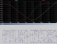
Attached below is a sim of one of my regulators for a current project. One the left is an ideal version with zero ohm ground and rail tracks, on the right is a somewhat less than ideal version with multiple (exagerated) 100m-ohm resistors distributed between each node of the ground track and the positive rail track.
PSR is the same in either case.
So long as there are no ground loops and the high current filter cap current on the unregulated side of the regulator do not share part of the ground track with the low current stuff, PSR isn't an issue.
Cheers,
Glen
Attachments
G.Kleinschmidt said:That will lower the output impedance, but it won't do anything for PSR.
On second thoughts I could have worded that better. It is conceivable that the grounding on the PCB is less than optimal in a way such that relocating the voltage sensing points may improve the PSR, but doesn’t discount the fact that the real cause of PSR degradation is in the ground layout.
Ripple currents from the unregulated side should not be flowing through the small-signal ground track(s).
Cheers,
Glen
G.Kleinschmidt said:
Ripple currents from the unregulated side should not be flowing through the small-signal ground track(s).
That shouldn't be too though, especially with a shunt reg, since a shunt reg splits the loops (raw supply and regulated supply) quite effectively.
Is there an irregular loop in the actual PCB-layout?
Rüdiger
I think that because of the non-infinite PSRR, some of the residual ripple that ends up on the output side, is shunted away by the shunt reg - at least it will try. That in itself will cause ripple currents through the shunt return, although this may be too small to really matter in the end.
Fact is that I measured at least 20dB improvement in PSRR when measured directly at the sense string.
Jan Didden
Fact is that I measured at least 20dB improvement in PSRR when measured directly at the sense string.
Jan Didden
This is the latest schematic. Still needs the last few changes to be added.
http://www.diyaudio.com/forums/showthread.php?postid=1733072#post1733072
🙂
http://www.diyaudio.com/forums/showthread.php?postid=1733072#post1733072
🙂
- Status
- Not open for further replies.
- Home
- Amplifiers
- Solid State
- Bipolar discrete shunt regulators