I think you will find it operates at a very much lower Vdrop than 2V.00940 said:
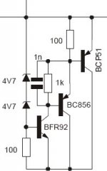
The cascoded CCS works with as low as 2V with a 1n4148 instead of the 100R
Add the V across the two CCS voltage references. A red LED=1.55V and 100r passing 3.3mA drops 330mV.
The base of the cascode sits at 1.88Volts below the input voltage.
The emitter must sit at about 600mV above this, i.e. 1.28V below the input voltage. Check the saturated voltage for a 340/350 @ your chosen CCS current. It'll be around 0.1 to 0.2V.
The minimum volts drop is ~1.28+0.1V to 1.28+0.2V
Let's say about 1.4V
If LDO is important pick transistors that operate with very low Vce and a low Vbe at your chosen current and reduce the red LED ref. voltage by using a series pair of diodes, [0.65+0.65V] saves a further 0.25V giving a drop ~1.15V.
The cascode will not operate ideally with this tiny voltage across it but it's job is to protect the first transistor from voltage variations. Then the CCS works very well.
AndrewT said:Sorry we're close but not yet in agreement on the arithmetic.
Does a 20V through a 1k0 resistor give +-28mApk?
The 75mA draw of the shunt regulator has to supply Iq. Iq is ~13mA through the CCS and ~3mA through R5. This leaves ~59mA to feed the load and the shunt and the test current source/sink.
Using your 1k3 load with 30V across it, the load sinks 23mA. That leaves 36mA to go through the shunt and the current source.
So the nominal shunt current is 36mA+-28mA i.e min~8mA and max~64mA.
Are we in agreement yet?
If we reduce the load resistance to 1k0 and sink 30mA
then the shunt varies from {[75-16] -30]}+-28.4mA~=0.6mA to 57.4mA
I see a problem, the minimum shunt current gets very close to zero and depends very much on a difference of two similar but large currents.
There's the reason for my original question. I fear we must be very careful to ensure the test AC current source/sink does not take the shunt beyond it's operational limits.
Yes agreed. BTW 20V was what I said, you said 28Vpk so I assumed you converted my 20V (RMS) to pk. 😉
I like to test close to the limit. I don't worry about the last mA, because it can easily be adapted to the actual situation if necessary. My 20mA (RMS) test current is chosen as large as I find reasonble to have anything to measure at all.
If you get too close, you immediately see on the scope if you run out of regulation: instead of very small (<1mV) ripple all of a sudden you see volts!
Jan Didden
Once the correct differential reached and up, the cascoded CCS simulate better but not that much for PSRR (a pair of db). I guess I should try other things (dynamic load) to see the advantages of cascoded CCS.
The cascode is biased by a simple resistor and sees the ripple of the raw supply, and it may be sensitive to ripple? In your sims, can you replace R5 with a simple current sink (5mA Jfet for example) and see how this improves PSRR?
Hello
I think that this Thread is very good and interesting learning, but
I have taken this shuntreg from an old zapfilter (Lcaudio) I know it´s sound very very good, using it in my modified cdplayer.
It gives constant 10V out.
The Shuntreg is supplied like this:
Transformer-> Rectifiers-> serie resistors to set the current flow-> shuntreg -> load
Trans BCP51 take 100mA by it self (sinks)
Can some off you simulate this??
Eks: 15V DC supply, Current to circuits 150mA (100mA BCP51 and 50mA pulled by load.
Kim
Attachments
MRupp said:The cascode is biased by a simple resistor and sees the ripple of the raw supply, and it may be sensitive to ripple? In your sims, can you replace R5 with a simple current sink (5mA Jfet for example) and see how this improves PSRR?
With an ideal current sink, PSSR for the cascoded CCS improves by 30db at audio frequencies. Above it is less significant. The single transistor CCS improves by only 15db.
But I still need a big voltage drop to get it working. LTspice has most probably difficulties to simulate transistors in saturation ?
00940 said:
But I still need a big voltage drop to get it working. LTspice has most probably difficulties to simulate transistors in saturation ?
I can't comment on LTspice, but with a very similar CCS (with an jfet CS in place of R5 and a LED in place of that 100R resistor) you'd better allow more then 5V across it in order to get maximum stabilty and regulation in the real world. (I happen to have 22V in and 15 V out, or over 30V in and 24V out in a more or less simliar design)
Rüdiger
I agree with Rüdiger, if you can afford the extra voltage drop you should have a healthy voltage margin on the regulator. Now for the real world sink I have a few suggestions:
We should replace the ideal sink with: Either with a (more expensive) current diode or a self-biased Jfet like a BF245A which are available and cheap (ebay). This is simple and can be done on the existing board (though it would look better with proper layout).
If you wanted to improve that you could cascode it with BF245C (higher current and pinch-off voltage) and maybe even put a small biasing resistor under the source of the first JFET. But this requires a board layout change.
Alternatively and more in vein with the current design we could try to convert the cascoded current source (Q5 / Q7) & sink into some kind of current source dipole, with another LED under R2, and a NPN transistor with a biasing resistor at it’s emitter under R5. If we wanted to improve this we could simply cascode it, basically a mirror image of Q4 and Q7.
Has anybody already done any input rejection ratio measurements for the existing or other configs so we know what we are talking about?
Jan Didden
Jan Didden
OK, did some measurements on the reg that I got from Tony.
I put 100 ohms in series with input voltage, then injected AC sine wave at the regulator input.
Did two measurements at 1kHz and 10kHz:
1kHz: input 100mV, residual at output: 2mV, PSRR 50x = -34dB
10kHz: input 30mV, residual 2.4mV, PSRR 12.5X = -22dB
Then I replaced the 100 ohms in the series CCS with a diode, for reasons mentioned earlier:
1kHz: input 100mV, residual at output: 1.6mV, PSRR 63x = -36dB
10kHz: input 30mV, residual 2.2mV, PSRR 17X = -22.7dB
This is all measured directly at the output cap.
Comments?
Jan Didden
seems very low PSRR.
Is the PSRR dependent on output current?
What about an AC cap across R8 and increasing C1?
Is the PSRR dependent on output current?
What about an AC cap across R8 and increasing C1?
AndrewT said:seems very low PSRR.
Is the PSRR dependent on output current?
What about an AC cap across R8 and increasing C1?
Yes it is very low. Increasing C1 might help but max 6dB. I did decrease R8 rather than putting a cap over it. Actually, my measurements are with R8=120 ohms. I tried shorting R8 but that leads to strong oscillations. Probably there is still something to gain with finding the lowest R8 that still is stable. (Note that I have a 12V zener in series with R8 to improve the regulation).
Jan Didden
What do you think, is it the 'regulator'-part or the CCS that is flawed? Or both?
My suggestion is that the CCS needs improving. I was rereading Walt Jung's articles on current sources (on his WEB pages, very good read!) that include numerous different topologies and PSRR measurements on all topologies presented. His testsetup was basically the same he used for his "super-regulator" development. His best PSRRs values were limited by the noise floor of the test rig and show what can be achieved. One conclusion is to "always operate the current source with sufficient voltage headroom", so a diode in place of the 100 Ohm may not be enough (Morgan Jones suggests 2V VCE or better more at higher currents).
In part 2 Fig. 14A and B he compares a TLV431 based CCS (different from ours off course), biased from supply firts via a 100K resistor, then a simple CCS, then a cascoded current source. Not that we should change the LED to TLV431, but look at the improvements with CCS bias.
Another good read on current sources is in Morgan Jones' book. One important suggestion is to select the correct transistor for the CCS. hfe is directly related to the impedance, so selecting a transistor that is operating within it's optimal hfe vs. current range is important. For a current of ca. 70 mA the BD139/BD140 may just be suboptimal and a small signal type might be better. I am not suggesting to alter the topology but just choose the right transistor for the particular current requirement. A further point is to have sufficient bias current across the LED so that it is much higher than the base currents (just an idea).
P.S. If you you would like to test the effect of biasing the LED with a CCS I would offer to supply a couple of J511 current diodes to replace R5.
Martin, good points.
I would also increase the Vce, both in the CCS and the cascode load. Someone suggested using a LED here instead of 100 ohms and I'll try that next.
Another issue is the relatively low loop gain. With R8 and R7 120 ohms, Q1 doesn't contribute anything, just level shifting.
I'll take a look at the min R8 for a stable loop. Increasing R7 might also be a good optimization, as well as decreasing R5. You want to make the CCS biasing as little dependent on the various base currents and just increasing the bias current through D1/R3/R5 can make an important improvement.
Jan Didden
it's funny cos on post one of this thread the spice simulation shows ripple rejection to 1 meg hz is about 100db
mmmm
that's a big discrepancy
or did I mis-interpret that graph ?
mmmm
that's a big discrepancy
or did I mis-interpret that graph ?
What I have is a LED in place of R3, and R5 replaced by a jfet (2sk246) set to ~4mA and hooked to the collector of Q6. But I did not perform Jan's test yet. Q5 is BD140, Q6 is MJE15031, used it between 50 - 200mA.
Rüdiger
Rüdiger
janneman said:Another issue is the relatively low loop gain
If high PSR is your goal just isolate the load capacitance with a small series damped inductor and ramp the loop gain up as high as you can. Most low power applications won't be bothered by an output impedance of a couple of tenths of an ohm or so at LF, and the LC low-pass does wonders for RF PSR (not to mention the possibility of an additional one at the regulator input as well).
Cheers,
Glen
Yeah - I'm a big fan of inductors to block RF junk . . .
. . . . but if the PSRR is as bad as Jan says it is then I think we need something more radical that deals with the entire frequency band from DC to 1 meg hz
mike
. . . . but if the PSRR is as bad as Jan says it is then I think we need something more radical that deals with the entire frequency band from DC to 1 meg hz
mike
mikelm said:. . . . but if the PSRR is as bad as Jan says it is then I think we need something more radical that deals with the entire frequency band from DC to 1 meg hz
That's what I was getting at. More loop gain will get you better PSR, but there is a practical limit on loop gain if the load capacitance isn't isolated one way or another.
Cheers,
Glen
- Status
- Not open for further replies.
- Home
- Amplifiers
- Solid State
- Bipolar discrete shunt regulators